

The Wildland Fire Chemical Systems (WFCS) program tests a variety of fixed- and rotary-wing tankers to determine the parameters for optimal ground pattern coverage over a wide range of fuel and fire conditions. The Snow Air Tractor AT-802F, owned and operated by Queen Bee Air Specialties, is one of a family of smaller airtankers used for initial attack fire suppression.
The Snow Air Tractor fire retardant door system contains a constant flow tank made of stainless steel. The 800-gallon single tank is divided into two hoppers with a connecting lower section. Two opposing doors that hinge on the airtanker's longitudinal axis are used to control the flow. The drop system control panel allows the pilot to select coverage level settings of 0.5 to 4 (77 to 450 gal/sec) or a salvo drop, which opens the doors completely. A hydraulic system actuates the door opening. The control system specifies the amount of retardant to be dropped, coverage level, and ground speed. Tests included airspeeds from 78 to 87 knots (90 to 100 mph) and drop heights from 40 to 113 feet (measured from the bottom of the tank to ground). The drops were made with three different materials: water, foam, and gum-thickened retardant.
The Missoula Technology and Development Center tested the Snow Air Tractor (Figure 1) with a series of drops over an array of plastic bowls much like Cool Whip containers. The quantity of material in each bowl was measured and the data were used to determine the drop pattern.
|
| Figure 1-The constant flow tank in the Snow Air Tractor. |
Flow rate, drop height, and airspeed affect the drop pattern. Increasing the drop height gradually widens the drop while decreasing the coverage levels. This effect is modified by the ambient wind. Increasing windspeed widens the drop and decreases coverage levels. Increasing airspeed increases the line length while reducing the coverage level.
Because this airtanker has variable flow rates, it can produce specific coverage levels needed for accurate drops using all of the liquid in the tank. Figures 2, 3, 4, 5 and 6 show the effect of increasing the coverage level setting from 0.5 to 4.
 |
| Figure 2-Drop pattern characteristics for the Snow Air Tractor with a coverage level setting of 0.5, an airspeed of 85 knots (98 mph), and a drop height of 46 feet. The contour lines are at coverage levels of 0.5, 1, 2, 3, 4, 6, 8, and 10 gallons per 100 square feet. |
 |
| Figure 3-Drop pattern characteristics for the Snow Air Tractor with a coverage level setting of 1, an airspeed of 85 knots (98 mph), and a drop height of 90 feet. The contour lines are at coverage levels of 0.5, 1, 2, 3, 4, 6, 8, and 10 gallons per 100 square feet. |
 |
| Figure 4-Drop pattern characteristics for the Snow Air Tractor with a coverage level setting of 2, an airspeed of 87 knots (100 mph), and a drop height of 99 feet. The contour lines are at coverage levels of 0.5, 1, 2, 3, 4, 6, 8, and 10 gallons per 100 square feet. |
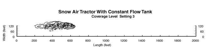 |
| Figure 5-Drop pattern characteristics for the Snow Air Tractor with a coverage level setting of 3, an airspeed of 81 knots (93 mph), and a drop height of 110 feet. The contour lines are at coverage levels of 0.5, 1, 2, 3, 4, 6, 8, and 10 gallons per 100 square feet. |
 |
| Figure 6-Drop pattern characteristics for the Snow Air Tractor with a coverage level setting of 4, an airspeed of 78 knots (90 mph), and a drop height of 113 feet. The contour lines are at coverage levels of 0.5, 1, 2, 3, 4, 6, 8, and 10 gallons per 100 square feet. |
The proper amount of fire-retarding material (expressed as coverage levels in gallons per 100 square feet) differs depending on the fuel model. Table 1 shows the coverage needed for specific fuel models using both the National Fire Danger Rating System (NFDRS) and the Fire Behavior Fuel Model.
Table 1-The retardant coverage needed for specific fuel types.
| Fuel Model | |||
|---|---|---|---|
| National Fire Danger Rating System (NFDRS) | Fire Behavior | Coverage Level (gal/100 sq. ft) | Description |
| A, L, S | 1 | 1 | Annual and perennial western grasses, tundra |
| C | 2 | Conifer with grass | |
| H, R | 8 | 2 | Shortneedle closed conifer; summer hardwood |
| E, P, U | 9 | Longneedle conifer; fall hardwood |
|
| T | 2 | Sagebrush with grass | |
| N | 3 | Sawgrass | |
| F | 5 | 3 | Intermediate brush (green) |
| K | 11 | Light slash | |
| G | 10 | 4 | Shortneedle conifer (heavy dead litter) |
| O | 4 | Southern rough | |
| F, Q | 6 | 6 | Intermediate brush (cured), Alaska black spruce |
| B, O | 4 | California mixed chaparral, high pocosin |
|
| J | 12 | Greater than 6 | Medium slash |
| I | 13 | Heavy slash | |
The results of drop tests allow managers to estimate the length of line a specific airtanker produces at various coverage levels. Table 2 or Figure 7 can be used to estimate the flow rate for a water drop to obtain the longest line of the desired coverage level. Table 3 or Figure 8 can be used to estimate the flow rate for a foam drop to obtain the longest line of the desired coverage level. Table 4 or Figure 9 can be used to estimate the flow rate for a gum-thickened retardant drop to obtain the longest line of the desired coverage level.
Table 2-Water tests producing the longest line at various flow rate settings using a constant flow tank.
| Coverage Level (gal/100 sq. ft) | Flow Rate (gal/sec) |
Coverage Level (setting) |
Drop Length (feet) |
|---|---|---|---|
| 0.5 | 77 | 0.5 | 1604 |
| 1 | 77 | 0.5 | 1075 |
| 2 | 277 | 2 | 484 |
| 3 | 277 | 2 | 339 |
| 4 | 405 | 3 | 262 |
| 6 | 405 | 4 | 102 |
| 8 | 450 | 4 | 28 |
| 10 | 450 | 4 | 10 |
 |
| Figure 7-Use this graph to estimate the flow rate needed to produce the longest line of water at various coverage levels. |
Table 3-Foam tests producing the longest line at various coverage level settings using a constant flow tank.
| Coverage Level (gal/100 sq. ft) | Flow Rate (gal/sec) |
Coverage Level (setting) |
Drop Length (feet) |
|---|---|---|---|
| 0.5 | 77 | 0.5 | 1602 |
| 1 | 140 | 1 | 940 |
| 2 | 277 | 2 | 437 |
| 3 | 277 | 2 | 319 |
| 4 | 405 | 3 | 171 |
| 6 | 405 | 3 | 31 |
| 8 | 405 | 3 | 2 |
| 10 | - | - | 0 |
 |
| Figure 8-Use this graph to estimate the flow rate needed to produce the longest line of foam at various coverage levels. |
Table 4-Gum-thickened retardant test producing the longest line at various coverage flow rate settings using a constant flow tank.
| Coverage Level (gal/100 sq. ft) | Flow Rate (gal/sec) |
Coverage Level (setting) |
Drop Length (feet) |
|---|---|---|---|
| 0.5 | 77 | 0.5 | 1710 |
| 1 | 77 | 0.5 | 1536 |
| 2 | 140 | 1 | 608 |
| 3 | 277 | 2 | 423 |
| 4 | 405 | 3 | 274 |
| 6 | 450 | 4 | 156 |
| 8 | 450 | 4 | 82 |
| 10 | 450 | 4 | 68 |
 |
| Figure 9-Use this graph to estimate the flow rate needed to produce the longest line of gum-thickened retardant at various coverage levels. |
The graphs predict line length (in feet) as a function of flow rate (in gal/sec). The tables are constructed by selecting the drop producing the longest line (on the ground) at each coverage level. Either the graphs or tables may be used to estimate the flow rate required to produce the longest line for a given coverage level. The tables show an ideal case, while the graphs represent an average.
 |
| Figure 10-Snow Air Tractor dropping fire-retarding material. |
For example, if a fire is burning in NFDRS Fuel Model C (Fire Behavior Model 2), represented by conifer with grass, a coverage level of 2 is required (Table 1).
The graph for gum-thickened retardant shows that for coverage level 2, a coverage level setting of 1 produces the longest line (608 feet).
The ground drop characteristics for the Snow Air Tractor were derived through controlled drop test procedures on flat ground (Figure 10). This information is to serve only as a guide to help field personnel determine the proper drop height, airspeed, and door opening for delivering water, foam, or gum-thickened retardant. Actual coverage may vary depending on terrain, wind, weather, and pilot proficiency.
Cammie Jordan is a Project Assistant for the Wildland Fire Chemical Systems Program at MTDC. She is an elementary education student at the University of Montana and has worked for MTDC since 1998.
Paul Solarz is Program Leader for the Wildland Fire Chemical Systems Group. He received his bachelor's degree from Eastern Oregon State College in 1986. Paul has worked in Aviation and Fire Management since 1973, serving at seven Ranger Districts and in two Forest Supervisor's offices. He has an extensive operational background in fire, fuels, and aviation.
Additional single copies of this document may be ordered from:
USDA Forest Service
Missoula Technology and Development Center
5785 Highway 10 West
Missoula, MT 59808
Phone: 406-329-3978
Fax: 406-329-4811
E-mail: wo_mtdc_pubs@fs.fed.us
For additional Information contact:
Greg Lovellette, Project Leader
Missoula Technology & Development Center
5785 Highway 10 West
Missoula, MT 59808
Phone: 406-329-4719
Fax: 406-329-4811
E-mail: glovellette@fs.fed.us
Lotus Notes: Greg Lovellette/WO/USDAFS
This page last modified June 14, 2002
Visitor
since June 14, 2002