| |
|
||
| |
June 2002 | |
|
| |
|||
| |
0251 1304-SDTDC | ||
| |
|||
|
|||||||||||||||||||||||||||||||||||||||||||||||||||||||||||||||||||||||||||||||||||||||||||||||||||
Lightweight
Pressure Regulator Lois Sicking,
Mechanical Engineer
INTRODUCTION Pressure
in a Downhill Hose Lay The ability to reduce pressure in a downhill hose lay and minimize burst hose is critical to firefighter safety. Loss of water supply to the nozzle means loss of fire protection to firefighters and restricted fireline construction and mopup. Assurance that a hose is not going to burst from high pressure provides a better margin of safety for firefighters. Forest Service fire hoses are constructed for a working pressure of 300 psi (2,064 kPa). A fire hose may develop areas of wear that do not support a pressure of 300 psi (2,064 kPa). When downhill pressure approaches 300 psi (2,064 kPa), safety dictates a pressure regulator be added inline to reduce pressure to between 50 and 125 psi (344 to 860 kPa). Lightweight
Pressure-Reducing Valve with Pressure Gage
The pressure gage has a range of up to 160 psi (1,101 kPa) and indicates the reduced pressure. This pressure regulator weighs 2.7 lb (1.2 kg). It contains an integral strainer screen, serviced by removing a plug. This bronze water pressure-reducing valve with a pressure gage also has an integral strainer and National Pipe Thread (NPSH) female threaded inlet and outlet connections. The pressure regulator (figure 2) has an inlet of 1 in (25.4 mm) and can be adapted to a larger diameter. It is recommended that an inlet to outlet diameter ratio of 10 to 1 not be exceeded. Consequently, this pressure regulator can be used with a 1-in (25.4-mm) or 1-1/2-in (38.1-mm) hose. The pressure level at which the regulator automatically functions can be adjusted by a screw and secured with a locknut. This pressure regulator should be adapted with a female thread adapter on the inlet and a male adapter on the outlet to make it fire ready.
Pressure-Reducing
Test Data
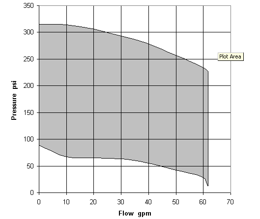
The results in table 1 show that at an initial hose pressure of 293 psi (2,016 kPa), pressure can be reduced to 63 psi (433 kPa) and can maintain a flow of 30 gal/min (114 L/min). This is a decrease in pressure of 230 psi (1,582 kPa), corresponding to a change in vertical elevation of 535 ft (166 m). This is calculated by 230 psi divided by 0.43 psi per 1 ft, or 1,582 kPa divided by 3.0 kPa per 0.31 m.
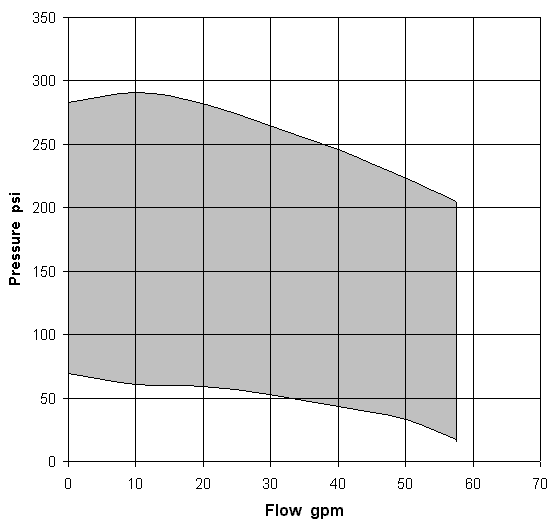
The results in table 2 show that at an initial hose pressure of 265 psi (1,823 kPa), pressure can be reduced to 53 psi (365 kPa) and maintain a flow of 30 gal/min (114 L/min). This is a decrease in pressure of 212 psi (1,459 kPa), corresponding to a change in vertical elevation of 493 feet (152.8 m). This is calculated by 212 psi divided by 0.43 psi per 1 ft, or 1,459 kPa divided by 3.0 kPa per 0.31 m. Findings Manufacturer
Information The pressure regulator tested was the Watts Model N35BGG, bronze water pressure reducing valve with pressure gage and integral strainer; valve pressure range from 25 to 75 psi, set at 50 psi, pressure gage range up to 160 psi; NPT female threaded inlet and outlet connections; weight of 2.7 lb; and costing $51 with the pressure gage and $49 without it. For further information or to share comments and recommendations for further study, contact SDTDC by phone at 909-599-1267 or by e-mail at Mailroom/wo_sdtdc@fs.fed.us. |
|||||||||||||||||||||||||||||||||||||||||||||||||||||||||||||||||||||||||||||||||||||||||||||||||||

Project Leader, Fire Management San Dimas Technology & Development Center 444 East Bonita Avenue, San Dimas CA 91773-3198 Phone 909-599-1267; TDD: 909-599-2357; FAX: 909-592-2309 E-mail: mailroom_wo_sdtdc@fs.fed.us Information contained in this document has been developed for the guidance of employees of the Forest Service, United States Department of Agriculture (USDA), its contractors, and cooperating Federal and State agencies. The USDA assumes no responsibility for the interpretation or use of this information by other than its own employees. The use of trade, firm, or corporation names is for the information and convenience of the reader. Such use does not constitute an official evaluation, conclusion, recommendation, endorsement, or approval of any product or service to the exclusion of others that may be suitable. The U.S. Department of Agriculture (USDA) prohibits discrimination in all its programs and activities on the basis of race, color, national origin, sex, religion, age, disability, political beliefs, sexual orientation, or marital or family status. (Not all prohibited bases apply to all programs.) Persons with disabilities who require alternative means for communication of program information (Braille, large print, audiotape, etc.) should contact USDA’s TARGET Center at (202) 720-2600 (voice and TDD). To file a complaint of discrimination, write USDA, Director, Office of Civil Rights, Room 326-W, Whitten Building, 1400 Independence Avenue, SW, Washington, D.C. 20250-9410 or call (202) 720-5964 (voice and TDD). USDA is an equal opportunity provider and employer. |