

Chuck Whitlock, Project Leader
Chuck Harding, Mechanical Engineering Technician
- MTDC's Underbuck
- MTDC's Underbuck (Continued)
- Assembly Instructions
- Using the Underbuck
- Acknowledgments
- Additional Information
- About the Authors
Underbucking tools (underbucks) enable crosscut saws to cut up from the bottom side of felled logs. Normally, logs are bucked (cut to length) from the top as they lie on the ground. Gravity feeds the saw down through the wood. Sometimes a log that is suspended off the ground needs to be cut from the bottom up. Usually, this is because the log has fallen in such a way that a cut from the top closes on the saw (binds), while a cut from the bottom may open, allowing the saw to operate freely. An underbuck supports the saw and allows a sawyer to cut upward, against gravity.
An underbuck supports the back of the crosscut saw (figure 1). When the sawyer applies slight downward pressure on the saw handle, the underbuck applies upward pressure on the other end of the saw, moving the saw teeth upward to saw the log.

Figure 1—The underbuck supports the back
of the crosscut saw and provides leverage
for making cuts from the bottom of a log.
Grooved ax handles and mechanical underbucks have been used for underbucking for many years. Underbucks created by blacksmiths serving oldtime logging camps were large and heavy. No company manufactures underbucks today. The Missoula Technology and Development Center (MTDC) was asked to design a simple, lightweight underbuck for use by wilderness and backcountry crosscut sawyers.
MTDC's UnderbuckUsing an antique underbuck as an example, MTDC recreated an underbuck that is inexpensive, lightweight, and easily fabricated. It features a 2-inch clamp weighing 8 ounces with a shielded steel pulley that can attach to an ax handle (figure 2). There is no manufacturer for the new underbucks. Assembly is simple following the directions included in this TechTip.
The parts were purchased from Reid Tool Supply Co.; P.O. Box 179; Muskegon, MI 49443; Phone: 800–253–0421.

Figure 2—The underbuck, which attaches to
the ax handle, features a 2-inch clamp with
a shielded steel pulley.
The components cost about $25, including shipping and handling (figure 3). We were not able to find another supplier that had all the parts and would sell them in small quantities.
-
CBL-990 steel pulley, 1 ¼-inch diameter, shielded
-
KT-405 No. 2 Kant-Twist clamp
-
HHW-0550 split washer, ¼-inch internal diameter by 0.487-inch outside diameter
-
HN-050 hex nut, ¼–20, 7/32-inch thick
-
HK-64050 button-head cap screw, ¼–20, 1-inch long
-
Two BDA-30 disc springs, 0.551 by 0.283 by 0.0315 inches

Figure 3—Parts that are needed to build an underbuck.
Basic tools (figure 4) and the ability to use the tools safely are required for underbuck assembly.
-
Drill press
-
Drill press vise
-
Ball peen hammer
-
Center punch
-
Small metal file
-
Drill bit, 1/8 inch
-
Drill bit, ¼ inch
-
Hex key, 5/32 inch
-
Wrench, 7/16 inch

Figure 4—Tools that are needed to build an underbuck.
Figures 5 to 12 show how to assemble the underbuck tool.

Figure 5—Center punch the clamp pin on both sides.
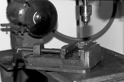
Figure 6—Secure the clamp in a vise to prevent it from moving.

Figure 7—Using a 1/8-inch drill bit, drill into the clamp
pin to a depth of ¼ inch. Turn the clamp over, secure
it in the vise, and repeat the process. This provides a
guide hole for the next step.

Figure 8—Drill both sides of the clamp pin with a ¼-inch
drill bit to a depth of ¼ inch, just clearing the side
plate of the clamp. Remove the clamp pin.

Figure 9—File all rough edges of the drilled holes smooth
with a metal file.

Figure 10—Insert the steel pulley and the two disc springs
between the side plates of the clamp.

Figure 11—Push the button-head cap screw through the drilled holes.
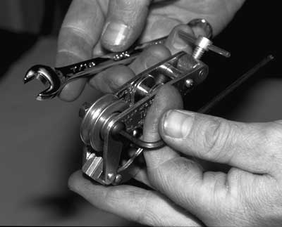
Figure 12—Place a lock washer and nut on the button-head cap
screw and tighten the nut, using a 5/32-inch hex key to secure
the cap screw and a 7/16-inch wrench to turn the nut.
Determine which side of the log is least likely to move once the log is bucked. Drive an ax in that side of the log in a position so the ax handle can serve as the support for the underbuck. An ax blade ground to a thin taper is more likely to stay in the log than an ax with a standard blade (figure 13). Place the blade of the ax so the last 6 to 9 inches of the ax handle are below the centerline of the log, directly below the top cut. The blade of the ax needs to be parallel to the log with the handle at a 30- to 45-degree angle to the log (figure 14). Getting this angle right takes practice, but the angle needs to allow room for the underbuck to be clamped onto the ax handle, the saw to be placed onto the underbuck, and the bottom cut to be started. If the ax is positioned correctly at the beginning of the cut, it will not need to be moved once the cut is started. Clamp the underbuck on the handle (figure 15) so the grooved sheave lines up with the top of the saw kerf.

Figure 13—A template for a sharpening gauge (reproduced
to exact size) and illustrations showing its use.
–Drawings by Frederic H. Kock

Figure 14—Insert the blade of the ax parallel to the log
with the handle between 30 and 45 degrees to the log.

Figure 15—Clamp the underbuck on the handle so the
grooved sheave lines up with the top of the saw kerf.
Thanks to Winston Rall, Pacific Northwest Region, and David Michael, Pacific Southwest Region, for their assistance and dedication to this project.
Additional InformationAdditional information on crosscut saws is available from MTDC:
-
An Ax to Grind: A Practical Ax Manual (9923–2823–MTDC)
-
An Ax to Grind (99–01–MTDC, video)
-
Crosscut Saw Tooth-Setting Tool (0223–2324–MTDC)
-
Crosscut Saw Manual (7771–2508–MTDC)
-
Handtools for Trail Work (8823–2601–MTDC)
-
Handtools for Trail Work (98–04–MTDC, video)
-
Crosscut Saw Guards (9723–2341–MTDC)
MTDC plans to publish a comprehensive user's manual for crosscut saws, written by David Michael, in 2003.
About the AuthorsChuck Whitlock (retired) has been a project leader at MTDC since 1998, specializing in safety and health and fire management safety projects. He has served as a type I safety officer on national incident management teams and a zone fire management officer on the Wallowa-Whitman National Forest. Whitlock has also worked on the Cleveland, Plumas, and Fremont National Forests before coming to the center.
Chuck Harding is a mechanical engineering technician in MTDC's equipment fabrication shop. He came to the center from the U.S. Air Force Reserve where he worked as a metals technology technician. He has been with the center since 2000.
Additional single copies of this document may be ordered from:
USDA Forest Service, MTDC
5785 Hwy. 10 West
Missoula, MT 59808-9361
Phone: 406-329-3978
Fax: 406-329-3719
E-mail: wo_mtdc_pubs@fs.fed.us
Electronic copies of MTDC's documents are available on
the Internet at:
http://www.fs.fed.us/t-d
For further technical information,
contact Chuck Harding:
Phone: 406-329-3364
Fax: 406-829-6757
E-mail: charding@fs.fed.us