
Anchorage System Design
The military has traditionally used cable anchorage systems for floating bridges that cross rivers. Only the most basic principles are covered here. Refer to chapter 8 of Military Float Bridging Equipment for more information. The Web address for that report is listed in the Additional Information section. The main disadvantage of a cable anchorage system is that cables typically need to be adjusted seasonally or more frequently, especially in areas with fluctuating water levels. In addition to the military designs, we have included typical dock and boardwalk anchorage systems suitable for Forest Service applications.
Submerged Anchor Cable SystemsBy far the most common anchorage system is an anchor cable combination. The total weight of the anchorage should be at least twice the weight of the structure being anchored. It is better if the weight of the anchorage is three times (even more when conditions are severe) that of the structure being anchored. Many small anchors will grip the bottom better and can be more easily adjusted than a few large anchors. The anchor line is referred to as the rode. The length of the rode is called its scope. Concrete blocks are the most commonly used anchor (do not use common concrete masonry bricks or cinderblocks). Anchor connections are spaced along the length of the floating bridge with more connections in areas subjected to higher stresses, such as section and shoreline connections. An anchor with a connecting rode is dropped off the side at each connection.
Anchors have the most holding power when the angle from the anchor to its attachment point is 45 degrees. Cross–chaining the anchors (attaching the rode to one side of the frame and placing the anchor on the opposite side) provides additional holding power. Rodes should not be under tension. They should provide enough scope so that the cable curves from the anchor to the bridge (figure 19). The curve allows for minor water level changes and bridge movement. Docks should have at least two (one on each side) anchors at the end. Docks exposed to severe weather should have a storm anchor placed in the direction of the prevailing winds with the rode attached to the dock's end and under slight tension.

Figure 19—Proper layout of a submerged anchor cable system.
Submerged anchor cable systems are not suitable for areas with fluctuating water levels such as reservoirs and tidal areas. Areas with smooth bedrock bottoms and sensitive habitats where anchors may harm desired species are also unsuitable.
Shoreline Anchor Cable SystemsMilitary floating bridges use a combination of submerged and shoreline anchors. Only a few of the more applicable types are covered here. Approach guys, also known as tension cables, connect the first section of the bridge to the shoreline. Cables run from the opposite corners of each section, preferably at a 45–degree angle, to shoreline anchorage points. If the bridge includes a ramp, these cables would crisscross under the ramp. They hold the bridge against the shoreline and reduce stress on the shoreline hinges or connectors. Tension cables allow for vertical movement and should have turnbuckles so they can be adjusted easily. Very often these cables run the entire length of the bridge to the opposite shoreline and function as the approach guys on both sides (figure 20). The advantage to this system is the tremendous lateral resistance it provides. However, if a section of the bridge needs to be removed the entire cable may need to be removed.

Figure 20—Running cables—or approach guys—from shore to shore along a
floating bridge provides an excellent means of anchorage.
Shore guys are similar to approach guys. The attachment points are farther out on the bridge and farther away along the shoreline. A 45–degree angle provides the most holding power. Longer shore guys will need flotation along their length to keep the cable or chain above the waterline. A qualified engineer should design approach and shore cable systems that will be under tension often.
Various methods exist for shoreline anchorage. Cribs, retaining walls, and solid structures work well. Holdfasts (natural anchorages such as boulders) also provide adequate holding power. Various types of deadmen (anchors buried on shore) or pickets driven into the ground at least 15 degrees away from the direction of pull will serve as anchors. Be sure that anchorage points will hold during severe conditions and that the design does not invite vandalism.
Overhead Anchor Cable SystemsThis military design may fit some Forest Service applications. Overhead anchor cable systems share features with conventional suspended trail bridges. A cable anchored on both shorelines is run over towers. The towers provide elevation. The elevated anchor cable runs parallel to the floating bridge and is upstream of it. Additional cables, called bridle lines, run from the anchor cable to attachment points on the floating bridge. The overhead cable system helps keep the bridge in position (figure 21), but does not provide lift.
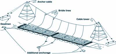
Figure 21—Basic parts of an overhead cable anchorage system.
Piles function as many different types of anchors. They can be substituted for submerged anchors. Drive piles close to the floating bridge, then hook the bridge to the pile for anchorage. Place hooks at different heights, have different lengths of cable, or include a turnbuckle on the cable so the bridge's position can be adjusted for different water levels.
Pile holders can be used to attach the bridge to the piles. External pile holders typically are a hoop or square that surrounds the pile with a solid bracket attached to the edge of the frame (figure 22). Square holders usually have bearings to reduce wear. A simple chain also will work, but the chain may increase wear on the pile. Internal pile holders are also available for piles that are placed inside the perimeter of the bridge. A pile system will reduce twisting forces on the shore connections and on the connections between sections of the floating structure. Piles are an excellent means of support for structures in areas where water levels fluctuate because they allow vertical movement while still providing anchorage. Their shortcoming is that they restrict horizontal movement. This may result in sections close to shore becoming grounded during periods of low water. The structure may be isolated during high water, making it inaccessible. These issues can be addressed by designing the shore access to accommodate changing water levels.

Figure 22—This dock uses multiple external pile holders for anchorage
(photo by Paul Schrooten, USDI Fish and Wildlife Service).
A variety of piles are available. Wood is the most common. Oil–based preservative treatments tend to perform better than water–based treatments when piles are submerged. Some municipalities require both types of treatment for piles used in saltwater areas. Oil–based treatments are not recommended for materials humans will contact and in certain environmental settings (usually very slow flow conditions). Decisions about which type of preservative to use need to be made on a case–by–case basis. Refer to the Additional Information section for more details.
Corrosion–resistant steel piles or concrete piles are also an option for pile anchors. Helical screws are also available. Helical screws are screwed into the ground using equipment that is small and portable.
Piles are set using three common methods. Piles can be driven using a pile–driving hammer, jetted into place by using a high–pressure stream of water to carve a hole, or grouted into holes that have been drilled, usually into bedrock.
Floating bridges and docks that use properly installed pilings and posts as anchors have an excellent chance of staying in place. The required depth and diameter of a pile depends on the size of the bridge and the forces acting on it.
Areas subject to heavy ice formation are vulnerable to pile failure. One national forest reported sinking piles 20 feet into the soil to support a boardwalk. During years of heavy ice formation, ice ripped the boardwalk and piling out of the ground. Tapered piles resist the upward pull of ice.
Another clever approach is to use a sleeved pile. First, set a traditional pile. Fit a hollow pile, with a bearing plate to hold the deck at its normal elevation above the water, over the first pile. As the ice pulls the deck up, the hollow pile will move up with the ice and drop back down as the ice melts (figure 23).
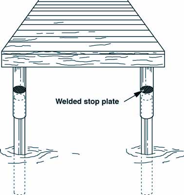
Figure 23—A sleeved pile should have a stop on the
exterior of the inside pile or on the interior of the
outer pile to keep the outer pile at the desired level.
Spuds are smaller than piles, often no larger than typical fenceposts. Spuds can be installed with manual fencepost drivers into softer bottoms or can be grouted into holes drilled into bedrock. Spuds can be wood or metal. Some have helical tips for screwing into softer substrates. Spud brackets tie the bridge to the spud. Spud brackets are similar to pile hoops, allowing the bridge to move up and down on the spud. Spuds are generally restricted to water depths of less than 5 feet.
Rail AnchoragesManagers faced with fluctuating water levels in inlet bays, reservoirs, or areas with seasonal flooding may want to consider rail anchorage systems. Many boat owners with waterfront property use a boat dolly set on a railway that extends into the water to remove their boats for the winter or for periodic maintenance.
This same principle can be used to adjust docks to fluctuating water levels. The Hells Canyon National Recreational Area in Idaho has such a rail anchorage system. See Engineering Field Notes, Vol. 22, January–February (1990) for additional information. The self–adjusting floating dock at Hells Canyon National Recreation Area uses a system that includes a dock connected to a trolley that rides on parallel rails set perpendicular to the shoreline (figure 24). A concrete weight counterbalances the downward force of the trolley on the dock, allowing the dock to adjust to the changes in river level. The trolley frame acts as the dock's anchorage, resisting lateral forces from currents, boat impacts, and other forces.

Figure 24—A representation of the rail anchorage system at
Hells Canyon National Recreational Area, ID.
For a longer
description of this image click here.
The secret to success for rail–based anchorage is in the details. The wider the railway and trolley, the more resistant they will be to forces acting on the dock. The site should be graded to provide an even slope from top to bottom. Be sure not to create a runoff path that could erode the support for the railway. The track also should be level from side to side. A concrete ramp, timber ties, or similar supports can be used to level the gradient. The rails themselves should be pinned, bolted, welded or somehow anchored so they do not shift. Backfilling the rails with gravel or rock once the railway is set provides even more holding power. Cross brace and diagonally brace the main steel beams of the frame.
Rail anchorage system designs are varied and widely customized. A trolley with hubs allows easy movement up and down the railway (figure 25). Some tracking systems use U–shaped metal channels wide enough for the trolley's wheels (figure 26). The forces created by waves, users, and currents have a tendency to derail the trolley.

Figure 25—It is easy to install trolleys using hubs
that roll up and down on round rails, but they are easily
derailed during severe conditions. Counter this problem
by using deep hubs, a heavy trolley, or another system.

Figure 26—Using deep U–shaped rail channels helps
keep the trolley on the tracks. The drawback to this system
is that debris accumulates in the channels, causing the
trolley to become stuck or derailed.
Other systems try to counter this problem. The trolley's wheels can be encased in a U–shaped beam, such as an I–beam (figure 27). Another possibility uses the wheel design of roller–coaster cars. A roller–coaster car has three wheels per set. One wheel rides on top of the track to carry the weight, one rides on the bottom to keep the coaster on the track, and one rides on the inside to help the coaster follow the track's path. Unless your track includes curves, omit the inside wheels. The distance from the track to the ground should be the bottom wheel's diameter plus 20 percent (to allow room for debris).
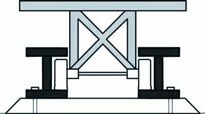
Figure 27—Rail systems based on an I–beam are
a common and effective trolley anchorage system.
Remember to design the dock to accommodate the trolley's weight. Use a counterweight similar to the system on the Hells Canyon dock or provide additional flotation on the dock. Added flotation increases the tendency for the trolley to derail. In such cases a tracking system that anchors the trolley to rail, such as the I–beam system, must be used.
A few other things to consider include using quality hardware such as galvanized cables and fasteners, and scheduling periodic maintenance. The system also requires periodic lubrication of the cables, pulleys, wheels, running surfaces, and hinges. The track should be kept free of debris.