
Refraction
Refractometers work on a principle known as light refraction. An example of refraction can be seen by putting a straw at an angle in a glass of water (figure 1). The straw bends slightly. If you put another straw in a glass of water containing dissolved sugar or salt, the straw would appear to be bent even more. The scale in the refractometer allows observers to measure the angle at which the light bends in a liquid.

Figure 1—Because of light refraction, a straw appears
bent when it
is in a glass of water. If the water is
replaced with concentrated sugar water, the straw
appears to be bent even more.
—Illustration
courtesy
of ATAGO U.S.A., Inc.
As the density of a liquid increases (such as when the salt concentration is higher in fire retardant), the liquid's refractive index (ability to bend light) increases proportionately. A refractometer puts this principle to practical use.
The hand-held refractometers found at airtanker bases use a transparent detection system (figure 2). A retardant sample with a lower salt content will give a larger angle of refraction (line a in figure 2). A retardant sample with a higher salt content gives a smaller angle of refraction (line b in figure 2).
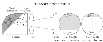
Figure 2—An illustration of the principles used in the
transparent
defection system of a hand-held refractometer.—Illustration
courtesy
of ATAGO U.S.A., Inc.
For a long description of this image click here.
Digital refractometers use a different method called a reflection system. This system is a bit more complicated. The explanation that follows is from the ATAGO U.S.A., Inc., Web site http://www.atago.net. In figure 3, light A, entering from the lower left of the prism, is not reflected back by the boundary, but exits through the sample. Light B is reflected by the boundary face to the right, directly along the prism boundary. Light C, entering the prism at too large an angle to pass to the sample side, is totally reflected toward the lower right of the prism.
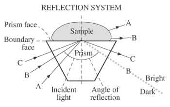
Figure 3—An illustration of the principles used in the reflective
detection system of a digital refractometer.—Illustration
courtesy of ATAGO U.S.A., Inc
For a long description of this image click here.
A boundary line is produced that divides light and dark fields on either side of the dotted line B in figure 3. Because the angle of reflection of this boundary line is proportional to the refractive index, the position of the boundary line between light and dark fields can be converted into the refractive index. (http://www.atago.net)