
Planning, Ordering, and Installing FRP Trail Bridges
In the Forest Service, the recreation program has the responsibility for planning and conducting environmental analyses for trail bridges. The forest engineer is responsible for ensuring that a site survey and hydraulic and geotechnical investigations are completed for each bridge site.
FRP trail bridges in national forests require specific approvals. The Forest Service Manual 7722 requires regional director of engineering approval of all "major and complex" trail bridges and forest engineer approval of all "minor" trail bridges. Because of their uniqueness, FRP bridges are considered a complex trail bridge (from the trail bridge matrix). The authority for designing and inspecting trail bridges falls under Forest Service Manual 7722 for design and Forest Service Manual 7736 for inspection.
All Forest Service FRP trail bridges should be added to the trails INFRA database, and inspected within the required inspection interval by qualified, certified bridge inspectors.
Planning
Proper planning for trail bridges should be a joint effort between specialists in recreation, engineering, and other resources. To ensure proper siting, include trail managers, hydrologists, soil scientists, archeologists, and wildlife biologists during planning.
Proper sizing and location of the bridge are an important part of its design. Consider adequate clearances for flooding and for ice and debris flow in the bridge's design and layout. The forest engineer is responsible for selecting the foundation and its design, along with the hydraulic design. A full hydraulic analysis for 100-year floods and debris is needed.
Types of Composite Bridges
FRP structural profiles are designed using traditional framing systems (such as trusses) to produce FRP pedestrian bridges. The selection and design of the truss system depends on the needs of the owner, the bridge's loading, and the site conditions.
The two basic types of FRP pedestrian bridges are the deck-truss and side-truss (pony-truss) bridges. Deck-beam FRP bridges have been used for boardwalks, but are rarely used for trail bridges (figure 6). Deck-truss bridges have fiberglass trusses and cross bracing under the deck with handrails attached to the decking (figure 7). Side-truss bridges have the superstructure trusses on the sides of the bridge. Pedestrians walk between the trusses (figure 8). Refer to the Trail Bridge Catalog (http://www.fs.fed.us/eng/bridges/) for more detailed descriptions of these bridges.

Figure 6—This boardwalk on Staten Island was
constructed using an FRP
deck-beam system.
—Courtesy of E.T. Techtonics, Inc.
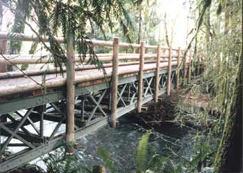
Figure 7—A deck-truss FRP bridge in Olympic National Park.
This bridge
uses FRP materials for the trusses and wood for
the
rails, maintaining a natural
appearance for a high-tech structure.
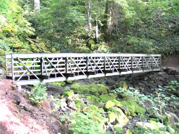
Figure 8—A side-truss FRP bridge in the Gifford Pinchot National Forest.
Bridge configurations are a major concern for longer spans. For spans of 30 feet or more, side-truss FRP bridges should have outriggers at all panel points (see figure 8) to provide lateral restraint for the compression flanges. FRP bridges longer than 60 feet that are used by pack trains should have a deck-truss design. That design places the trusses under the deck, increasing restraint on the compression flanges (see figure 7) and increasing the frequency characteristics of the bridge, an important consideration for the live loads generated by pack trains.
FRP bridges are not recommended for bridges longer than 50 feet in areas where snow loads are more than 150 pounds per square foot. The walkway wearing surface or decking can be designed using wood or FRP composite panels or open grating, depending on the bridge requirements.
Delivery Methods
Fully assembled bridges come as a complete unit and are delivered to the nearest point accessible by truck. A small crane or helicopter (figures 9 and 10) can place the bridge on its foundation. Decking may be shipped separately to minimize lifting weight. Depending on the location, shipping the bridge and decking separately may increase the shipping cost. Fully assembled bridges should be built by a contractor who has the heavy equipment required for this task.

Figure 9—A helicopter carrying a trail bridge.
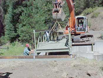
Figure 10—A track hoe placing a trail FRP bridge on its abutments.
Partially assembled bridges typically are delivered as individual assembled trusses. All other connecting components, such as crosspieces, bracing, and decking, are shipped separately. Sometimes carts, ATVs, or trailers can haul the trusses to the jobsite. This method is not suitable for moving trusses long distances or over rough terrain, but may allow a volunteer construction crew to transport the structure short distances and install it.
The most common approach is to have individual components shipped separately. They can be unloaded from the trucks by as few as two workers, usually at the trailhead or a nearby staging area. No special equipment will be needed to unload the components, and delivery of the bridge's components does not need to be coordinated with the bridge's assembly. Volunteers or force-account crews can carry the components to the bridge site. This method of construction works best for remote sites with limited access. Once everything is at the site, the bridge can be assembled easily using standard handtools. Spans up to 40 feet long usually can be built in less than a day by as few as three workers.
Things to Consider...
- Does an FRP bridge meet the visual, esthetic, or Built Environment Image
Guide (BEIG) considerations for this site?
- How long does the bridge need to be?
- What type of live loads will the bridge be subjected to?
- Will the bridge be used only by pedestrians?
- Will horses, pack trains, ATVs, snowmobiles,
motorcycles, bicycles, or other vehicles use the bridge?
- What are the snow loads for the area? Has a facilities engineer or local
building official
been contacted to learn the required snow loads for the area? Required snow
loads can be checked on MTDC's National Snow Load Information Web site
at: http://www.fs.fed.us/t-d/snow_load/ (Username: t-d, Password: t-d).
- What type of FRP bridge should be used (deck truss or side truss)?
- How wide will the deck need to be and what type of deck material should
be used? Should the deck include a wearing surface for horses, ATVs, or
snowmobiles?
- What type of railing system is required?
- Are wood curbs required to protect FRP trusses from ATVs?
- Will it be more practical to order the bridge fully assembled, partially
assembled, or unassembled?
- Have the plans been stamped by a professional engineer who has experience
with FRP and pedestrian bridge design? In the case of Forest Service bridges,
has the design been reviewed by the required authorities?
- What is the climate at the bridge site? What are the highest temperatures?
How long do those temperatures last? How much exposure to the sun will
the bridge receive?
- Is an FRP bridge the best type of bridge for this site?
- Is an FRP bridge the most cost-effective bridge for this site?
Ordering an FRP Trail Bridge
Some of the most important considerations before deciding what type of materials to use for your bridge are ease of construction, the weight of the materials, the risk of impact damage, and cost. Because an FRP deck or superstructure may cost more than wood and as much as steel, part of the scoping process involves evaluating all costs associated with a project, including the costs of all available types of material for the trail bridge.
An FRP trail bridge should be ordered using standard contract specifications. An example of a CSI specification from E.T. Techtonics, Inc., is included in appendix C. Other suppliers are listed in appendix G.
Transportation, Handling, and Storage
Transportation, handling, or storage problems can damage or destroy FRP components. Examples are shown in the section on Case Studies and Failures. Here are some tips for transporting, handling, and storing FRP materials based on the case studies and on the experience of the Trails Unlimited Forest Service Enterprise Team.
Tips
- Do NOT drag trusses across the ground.
- Make a skid or dolly
to haul trusses to the bridge site.
- Strap pieces together before hauling
them to the bridge site to prevent them from bending out of the intended
plane.
- Do
NOT scratch members. Repair all scratches with the sealant recommended
by the bridge manufacturer.
- Pick paths for hauling components to the
bridge site that will not require bending or twisting the components.
- Store all components flat, and support them with many blocks to prevent them from bending and to keep them off the ground so they will not be damaged by water and dirt.
Construction and Installation
Bridges can be delivered fully assembled, partially assembled, or in pieces. Typically, bridges for remote sites are delivered to the trailhead or to the district shop (figure 11).

Figure 11—FRP bridge materials being delivered to a staging area.
In most cases, short spans can be installed quickly by volunteers or work crews who assemble the two trusses near the crossing. Two workers can assemble the trusses of a simple 40-foot bridge. A larger crew will be needed for a short time to carry or pull the trusses to the bridge foundation, to carry some materials to the far bank, and to stand the trusses up on the foundations (figure 12).

Figure 12—A skyline system can be used to haul bridge
materials to an abutment across a stream.
Cross pieces and bracing are bolted underneath, connecting the two trusses. Bolting the cross pieces and bracing can take several hours if all work must be done from the deck level, but may not take as long if some portions of the bridge can be reached from below. Finally, the decking and safety rails are installed.
When the stream is not far below bridges with long spans, the easiest method of installation is to use construction lumber for several temporary supports (figure 13) in the streambed. Bottom chords, posts, diagonals, and the top chords are added in sequence until the bridge is fully constructed on the foundations. A small hydraulic jack or pry bar may have to be applied at the panel points to align the bolt holes. Supports are removed and decking is added.

Figure 13—Sometimes, temporary supports must
be used when constructing longer bridges.
The manufacturer should provide step-by-step assembly instructions. Assembly instructions for the Falls Creek Bridge are included in appendix I.
This type of assembly is appropriate for volunteer groups with experience using handtools. A small crew can install a 50-foot side truss trail bridge easily in 2 to 3 days using this method. Volunteers must be properly trained to prevent damage to the FRP components.
When the stream is far below bridges with long spans, installation usually is left to experienced contractors. Typically, trusses are assembled near the site and pulled across individually using "skylines" attached to trees near the streambank (see figure 12). This type of construction requires rigging experience. On some sites, a helicopter may be needed to lift the trusses into place (see figure 9).
The following tips were suggested by Forest Service personnel who work for the Trails Unlimited Enterprise Team.
The following tips were suggested by Forest Service personnel who work for the Trails Unlimited Enterprise Team.
Tips
- Study the drawings and the installation plan ahead of time. Consider laying
the components out in the approximate order in which they will be installed.
This will help workers become familiar with the components and their order
of installation. Try to have an experienced installer at the site.
- Ensure that you have the correct components and that they are oriented
correctly.
- Follow the manufacturer's instructions and the installation sequences.
- Measure and stake the bridge abutment work sites (figure 14).

Figure 14—Staking out a bridge site with a cloth tape.
- Clear and level the abutment work sites (figure 15).

Figure 15—Clearing an abutment with a small trackhoe.
- Verify the bridge's measurements and layout before constructing the bridge abutments (figure 16). Improper abutment construction has contributed to many bridge failures. Abutments need to be designed by engineers and constructed as designed to prevent failure.

Figure 16—Constructing an abutment for an FRP bridge.
- In tight working conditions, be especially careful to carry the correct end of long members in first.
- Assemble bridge trusses at an assembly site or near the bridge abutments (figure 17). When assembling trusses, use a tapered bar and a straight bar to line up the bolt holes (figure 18). Tap bolts lightly. Start a bolt at each side and use the mounting bolt to force the alignment bolt or straight bar out. Build as much of the top and bottom chords as can be handled before setting the trusses into place. The added stiffness will make construction easier. Bolt heads should always be on the inside of the top chord and on the outside of the bottom chord. If you have to use force to drive the bolts, something is out of alignment. No bolts should have to be driven except for the deck bolts that pass through the wooden decking and into the top flange. Bolts should not be more than finger tight.

Figure 17—Assembling a truss on level ground near the bridge site.

Figure 18— A tapered bar can be used to align bolt holes.
- Set trusses upright (figure 19) and haul them into place. Based on our experience, trusses carried upright will not flex as much as if they were carried flat and are less likely to be damaged. (Manufacturers say that trusses won't be damaged by flexing and can be carried more easily and safely when they are carried flat. Several people should carry each truss so it's not just supported at the ends.)
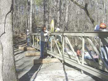
Figure 19—Trusses are set upright before being moved into place.
- Install the bridge clips on the abutments and position the completed trusses on the abutments. Square up the trusses and make sure they are parallel to each other (figure 20). Take measurements and verify them. Make sure that all members are in alignment and that all outriggers are installed at the proper locations. Install the bridge clips to keep the trusses upright and finger tighten the bolts.

Figure 20—Squaring up bridge trusses.
- Put the three deck boards that have carriage bolts in place: one near each end of the bridge and one in the middle. Leave the bolts loose enough to allow the decking to be adjusted. Install the cross and diagonal bracing between the bottom chords and finger tighten the bolts (figure 21).
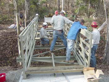
Figure 21—Installing and fastening cross bracing.
- Place planks on the bridge (figure 22) except for the two end pieces, which should be left off until the bridge clips have been tightened.

Figure 22—Workers fasten deck planks.
- Set the bridge's camber using a cross member and a hydraulic jack. Make sure not to lift the truss off the abutment (bolts are only finger tight at this point). Tighten the bolts until the lock washers are compressed (flattened) or until fiberglass begins to deflect. Do NOT overtighten because fiberglass will crack (figure 23).

Figure 23—Overtightening bolts cracked two tubes.
- Tighten truss bolts from the center out and from the top to the bottom.
Tighten the center bolts first, bolts at the first panel point on the right,
bolts at the first panel point on the left, bolts at the second panel point
on right, bolts at the second panel point on the left, and so forth. Tightening
bolts in this order is essential for load transfer and proper functioning
of an FRP trail bridge. Follow all of the manufacturer's instructions
and guidelines.
- Check the bridge's camber (figure 24) and adjust the bridge as necessary to get the camber as close as possible to specifications. Longer bridges require more precise camber.

Figure 24—A tape measure can be used to
check a bridge's camber
and deflection.
- Fasten planks to the bottom chords and stringers.
- Tighten the bridge clips to the sills.
- Place treated timber backwalls at the ends of the bridge and fasten them
in place, compacting the soil around the backwall. Use two to four stainless-steel
screws to secure the backwall. Backwalls may move over time, particularly
if the bridge is used for horses, mountain bikes, and off-highway vehicles.
- Place the end planks on the bridge and fasten them down.
- Use touchup paint for damaged areas. In extreme cases, it may be wise to
spray sealant over the entire structure, encapsulating the bridge. Damaged
members must be repaired or replaced before removing any temporary supports.
- Fasten the wood rails to the side trusses.
- Bolted connections will loosen over time because of vibration. Repeated
bolt tightening helps maintain the bridge's strength. However, overtightening
bolts cause various kinds of damage to FRP materials. Do
NOT overtighten.
Tighten until lock washers are compressed, or until the fiberglass begins
to deflect. Retighten the bolts every 5 years.
- Do not remove any members of the completed bridge (figure 25) after the temporary supports have been removed—doing so can lead to deflections and forces for which the bridge was not designed, possibly causing the bridge to fail.

Figure 25—The finished FRP bridge.
Safety and Tools
In the Forest Service, a Job Hazard Analysis (JHA) must be completed for every project. Follow the JHA recommendations for personal safety equipment, as well as direction in the Health and Safety Code Handbook, and the manufacturer's assembly instructions (example installation instructions are in appendix I). Wear hardhats, steel-toed boots, gloves, and safety glasses during construction. Tools required for installation and inspections are typically simple carpentry tools, such as hammers, tape measures, levels, socket wrenches, tapered drift pins, and screwdrivers (figure 26). Carbide drill bits and saw blades are best for drilling or cutting FRP materials.
