

David E. Michael, Trails Program Manager, Tahoe National Forest;
Mary Ann Davies, Project Leader
Chopping tools need to be sharp before they can be used safely and efficiently. The cutting edges of axes and Pulaskis used on the trail or fireline can take a beating if they are not used properly. Dull tools can ricochet off their intended target, striking and injuring workers. When a tool is damaged, it may need substantial filing or grinding (figure 1) before it can be restored to a serviceable condition.
- Sharpening heavily used axes and Pulaskis by hand can be tedious work.
- A new bracket that allows a narrow belt sander to be used like a draw file can make
sharpening much easier.
- This tech tip includes a reduced drawing of the bracket and instructions on how to use the bracket with a narrow belt sander when sharpening single- and double-bit axes and Pulaskis.
Field crews typically use hand files to sharpen their tools. Some crews finish with a polishing stone, honing the blade to remove the wire edge and burrs left after the filing. Sometimes rotary grinders are used to do the job more quickly. If a rotary grinder isn't used properly, it can overheat the tool's blade, weakening the edge. It is also difficult to maintain the proper blade angle when using a rotary grinder.

Figure 1—A newly developed bracket allows a narrow
belt sander to be
used much like a draw file for
sharpening axes and Pulaskis.
Other crews that demand a more precise cutting edge use a technique known as draw filing. In draw filing, the toe of the file is clamped into a holder that pivots on the head. After adjusting the height of the holder to set the bevel angle, the filer presses down and draws the file across the blade. The holder assures that the bevel angle will be uniform as the edge is sharpened.
The Missoula Technology and Development Center (MTDC) was asked to fabricate a bracket to fit a commercially available belt sander and evaluate the modified belt sander's effectiveness for sharpening chopping tools. This tech tip describes the newly developed bracket (figure 2, drawing MTDC–1064) that allows a commercial sander with a narrow belt to be used like a draw file.

Figure 2—Drawing MTDC–1064, "Ax Sharpener."
Grind a 45-degree tip onto one end of the 4-inch-long threaded post (part No. "3" on figure 2). Attach the knob (part No. "4" on figure 2) on the blunt end of post and secure it with glue.
The bracket (part No. "2" on figure 2) is constructed of 1 ½- by 1 ½-inch angle aluminum that is 1/8 inch thick.
Thread a wing nut onto the threaded post and thread the post into the 3⁄8 inch-diameter hole on the top of the aluminum bracket. Thread a locknut on the post under the aluminum bracket. The wing and locknut can be adjusted to change the angle of the aluminum bracket, changing the angle of the sanding belt.
Fastening the Bracket to the Belt SanderThe Makita Model 9031 belt sander (figure 3) comes with a side grip handle that attaches with a hex nut and two wave washers (figure 4). The MTDC bracket fastens to the Makita belt sander in the same manner as the original handle. Detach the side grip handle from the Makita belt sander by unscrewing the hex nut. Don't lose the two wave washers. Two holes drilled into the side of the MTDC bracket allow it to be fastened to the sander. The larger hole accepts the hex nut (don't forget the two wave washers). The smaller hole helps align the bracket. Tighten the hex nut (figure 5).

Figure 3—The commercial 1 1⁄8 inch-wide belt
sander (Makita Model 9031)
used for sharpening.

Figure 4—The hex nut and two wave washers attach
the
original side
grip handle or the new bracket to the sander.
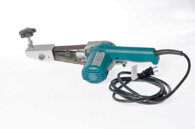
Figure 5—The new bracket attached to the
narrow belt sander.
Because the bracket on the belt sander pivots, the sander will move in an arc. The pivot point needs to be in the correct spot to maintain the original manufacturer's blade shape. The correct position of the pivot point only has to be determined once.
To determine the correct position for the pivot point of a symmetrical tool head, such as a double-bit ax or the ax portion of a Pulaski, you need to find the geographical center of the tool head. Use a flexible ruler to draw two diagonal lines across the face of the tool head. Start from the outer edge of the handle opening. Where the lines intersect is the geographical center of the toolhead (figure 6).

Figure 6—To determine the pivot point for a double-bit
ax, you must
determine the geographical center of the
ax
head. To find the geographical
center of the tool head,
use a flexible ruler to draw two lines across the
face
of the
tool head. Start drawing from the outer edge of the handle
opening.
This point can be marked by striking the tool head with a center punch. For a permanent mark, use a drill bit to create a shallow, chamfered hole. This hole needs to be deep and wide enough to keep the point of the bracket's threaded rod from slipping off the tool head.
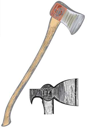
For some single-bit axes, such as the Rockaway, Hudson Bay, or Jersey, the blade's arc is not parallel to the handle. The following process, which requires a pencil compass (figure 7), will allow you to determine the correct position for the pivot point based on the blade's curvature.

Figure 7—For some single-bit axes, a compass is
used to
determine the
pivot point for a sander
fitted with the new bracket.
- Step 1: Using the pencil compass, place the compass point on the upper corner or toe of the bit. Place the pencil end of the compass about 1⁄8 inch toward the center of the bit from the poll and scribe an arc (figure 8).
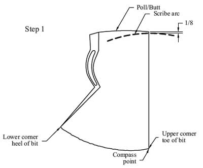
Figure 8—To find the pivot point of a single-bit ax, place
the compass
point on the upper corner of the bit. Adjust
the pencil point of the compass
about 1⁄8 inch
toward
the center of the blade from the poll and scribe an arc.
- Step 2: Using the same compass setting, place the compass point on the lower corner or heel of the bit and scribe an arc that intersects the previous arc (figure 9). The intersection is the pivot point.

Figure 9—Place the compass point on the lower corner of
the bit. Using the
technique in step 1, scribe an arc
with the pencil point to intersect the first
arc.
- Step 3: Place the compass point at the pivot point and make sure that the pencil follows the curvature of the blade’s edge when you pivot the compass (figure 10).
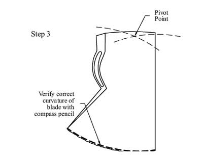
Figure 10—Place the compass point at the intersection
of the arcs and
sweep the pencil over the blade
to make
sure the pencil follows the
curvature of the
blade's
edge when you pivot the compass.
When the compass scribes the curvature of the blade correctly, mark and center punch the spot where the arcs intersect. Turn the tool head over and use the same compass setting to find the where the arcs intersect. Finally, drill a hole deep and wide enough to hold the point of the bracket's threaded rod. When the bracket is placed on this pivot point, the belt sander will follow the manufacturer's curvature of the blade.
Sharpening ToolsThe belt sander uses 1 1⁄8- by 21-inch sanding belts available in 40, 60, 80, 100, 120, 150, 180, and 220 coarse grit. When a tool is first sharpened or when a lot of metal needs to be removed during sharpening, use a belt with 40 or 60 coarse grit.
Place the tool to be sharpened at a comfortable height on a stable work bench with good lighting. Clamp the tool's handle securely to the work bench. The blade needs to extend slightly off the work bench so the sanding belt can move freely. Place the threaded rod of the bracket into the drilled pivot point on the toolhead. To change the angle of the sanding belt, adjust the lock and wing nuts on the threaded post.
Individual preferences for the bevel angle vary. On double-bit axes, a more acute angle, about 20 degrees, may be preferred on one of the bits with a blunter angle, about 40 degrees, on the other bit. Estimate the bevel angle and tighten the lock and wing nut.
When sharpening tools, wear proper personal protective equipment, such as leather gloves and eye protection. After sanding a few stokes on each side to create a bevel, use a bevel gauge (figure 11) to determine the desired angle before readjusting the bracket. Continue sharpening with the coarse belt until the bevel extends nearly to the edge of the blade. Without adjusting the bracket, turn the ax over and sharpen the other side of the blade until the bevel angle is reached. Finish grinding with a fine-grit belt to hone and polish the edge. The best way to remove the wire edge is with a fine-grit diamond stone that creates a microbevel (figure 12).

Figure 11—A Richard Kell bevel gauge can be used to
determine precise
blade edge angles or bevel. It
is
available from the General Services
Administration.

Figure 12—To finish the sharpening job, remove the
blade's
wire edge with
a fine-grit diamond stone.
A bracket, easily fabricated from standard aluminum, allows a narrow belt sander to sharpen single- and doublebit axes and the bit on Pulaskis. The bracket can be adjusted for different bevel angles. The bracket uses the principles of the draw filing technique, allowing the operator to fine tune the position of the sanding belt according to the tool's blade angle. The ease of fabricating and using this bracket makes it a handy addition to the tool kits of forestry field employees.
AcknowledgmentsIan Barlow of the Nez Perce National Forest deserves recognition for the idea for the bracket. Special thanks to Doug Lausch and Chuck Harding for fabricating prototypes in the MTDC metal fabrication shop and to Kris Kusano and Deb Mucci for engineering support.
About the AuthorsDavid E. Michael is the trails program manager for the Tahoe National Forest. He also serves as the crosscut saw coordinator for the Pacific Southwest Region of the USDA Forest Service and helped develop the Chain Saw and Crosscut Saw Training Course coordinated by MTDC. Michael has more than 35 years of experience in the woods, working for the Forest Service on the Tahoe, Apache-Sitgreaves, Coconino, Mt. Baker-Snoqualmie, Shasta-Trinity, Tongass, and Klamath National Forests in engineering, recreation, and wilderness management. He also worked in private industry as a timber consultant, cruiser, cadastral surveyor, vocational instructor, and logger.
Mary Ann Davies is a project leader at MTDC. She received a bachelor's degree in mechanical engineering with a minor in industrial and management engineering from Montana State University. She worked in the Forest Service's Pacific Northwest Region with facilities, tramways, recreation, and fire. Before coming to MTDC in 1998, she worked 5 years with the Rocky Mountain Research Station's fire chemistry and the fire behavior groups in Missoula, MT. Davies works on projects in the nurseries, fire, recreation, and watershed, soil, and air programs.
Additional single copies of this document may be ordered from:
USDA Forest Service
Missoula Technology and Development Center
5785 Hwy. 10 West
Missoula, MT 59808–9361
Phone: 406–329–3978
Fax: 406–329–3719
E-mail: wo_mtdc_ pubs@fs.fed.us
Electronic copies of MTDC's documents are available on the Internet at:
Forest Service and Bureau of Land Management employees can search a more complete collection of MTDC's documents, videos, and CDs on their internal computer networks at:
http://fsweb.mtdc.wo.fs.fed.us/search/
For additional information about modified belt sanders, contact Mary Ann Davies or David E. Michael:
Mary Ann Davies
Phone: 406–329–3981
Fax: 406–329–3719
E-mail: mdavies@fs.fed.us
David E. Michael
Tahoe National Forest
631 Coyote St.
Nevada City, CA 95959
Phone: 530–478–6183
Fax: 530–478–6109
E-mail: demichael@fs.fed.us