
Preliminary Engineering
Preparations for site investigations include collecting topographical maps, infrared photography, remote sensing images, geographical information system (GIS) coverages, and aerial photographs. Topographic maps (figure 2) can help when you are locating a bridge. They show contour lines of the proposed bridge site, the width and slope of the channel, and other important topographical features. Topographic maps may be ordered from the U.S. Geological Survey. Forest Service employees can download maps http://svinetfc4.fs.fed.us/clearinghouse/rastergateway/states/states.html.
Reviewing a number of years of aerial photographs and understanding stream types (figure 3) can help determine whether a stream is stable. Stable streams will show up in the same location year after year, while unstable streams may change locations or widths in photographs from different years. Two sources of free aerial photographs on the World Wide Web are Google Earth http://earth.google.com/ and Microsoft Virtual Earth http://www.microsoft.com/virtualearth/. Image quality varies from State to State. Aerial photographs can be purchased from the U.S. Department of Agriculture, Farm Service Agency aerial photography field office http://www.fsa.usda.gov.
Infrared photographs (figure 4) may show springs, wetlands, or other areas that are prone to being wet, helping designers avoid areas with poor foundation soils where trail and bridge construction is difficult and expensive.

Figure 2—Topographic maps can help when locating suitable sites for bridges.
When paired with aerial photographs (figure 3), topographic maps are even more valuable.

Figure 3—A series of aerial photographs taken during different years can help
show whether the stream is stable at a proposed bridge site.
This photographshows
the portion of Missoula, MT, displayed in the topographic map (figure 2).

Figure 4— Vegetation growing rapidly in areas that are prone to being wet will be
red
or orange in infrared photographs.
Site work includes site investigation, site surveys, and geotechnical investigations. Simple investigations are adequate for sites where the abutment locations are controlled by highways, railroads, lined ditches, canals, or dams (figure 5). Other bridge sites require a thorough investigation because of problems associated with stream dynamics, wildlife concerns, or other factors (figure 6). The more complex the site, the more important it is to form an interdisciplinary team. The team may include bridge and transportation engineers, geologists/geotechnical engineers, fisheries and wildlife biologists, hydrologists, botanists, archeologists, and soil scientists.

Figure 5—Some sites are very simple and require only minor siteinvestigation.

Figure 6—More complex sites require indepth investigation by an interdisciplinary
team.
Site investigation includes walking the upstream and downstream reaches and talking to long-time residents about flooding and debris jams. Some questions that should be addressed are:
- What time of year have floods occurred?
- How high does the water get? Does the stream flood over its banks?
- How much debris does the stream usually carry? Is damming a problem?
- Does the stream have ice flow problems?
During field reconnaissance, the stream should be reviewed for dynamic sections where the channel is moving (laterally and vertically) and problem areas that should be avoided, such as deltas, alluvial fans, actively aggrading/ degrading sections, sharp bends, multithreaded channels, sloughs, wetlands, and flood plains. Numerous photos (figures 7, 8, 9, 10, 11, and 12) should be taken of the proposed bridge site, banks, stream corridor, and other important features.

Figure 7—A photograph of trail location at a proposed bridge site
(Tombigbee National Forest).

Figure 8—A photograph looking at the site of one of the proposed abutments.

Figure 9—A photograph looking at the site of the other proposed abutment.

Figure 10—A photograph looking at a waterway at the proposed bridge site.

Figure 11—A photograph looking upstream from the proposed bridge site.

Figure 12—A photograph looking downstream from the proposed bridge site.
The ordinary high water (OHW) or bankfull stage indicators from flows expected every 1 to 2 years should be identified using geomorphic features in the field (Stream Systems Technology Center 2004). The stream bankfull depth and flows (figure 13) are used for hydraulic modeling and for verifying that the structure will be long enough. In figure 13, Q is the discharge in cubic feet per second. Videos showing how to determine bankfull stage can be viewed at http://www.stream.fs.fed.us/publications/videos.html or can be ordered at http://www.stream.fs.fed.us/.

Figure 13—Schematic showing how to determine the bankfull width. Flood stage height Q50-100 is about
twice the bankfull stage height Q1.5-2.
For streams with gauges measuring flows, the Q2/Qbankfull relationship can be determined using stream-gauge data to validate modeled flow projections. For streams that do not have a gauge, the bankfull flow determined using the bankfull indicators can be compared to the peak flow the model projects for every 1.5 to 2 years (the Q1.5-2 flow value).
Also, it is valuable to get a field estimate of the elevation that corresponds to large floods. This elevation can be checked with estimates of the flood peak flows expected every 50 to 100 years (Q50-100 flow value) to verify model projections. A rule of thumb used when estimating the flood depth is to determine the approximate maximum bankfull depth in a riffle and double it. This is the depth of the floodprone area in a representative channel section that might be flooded during a Q50 to Q100 floodflow. Design criteria that are affected by the floodflow and conveyance across the flood plain include minimum clearances for water and debris, areas where erosion and flooding might be a concern, and the types of trail tread that should be required on the approaches.
The stream should be investigated for at least 1,500 feet upstream and downstream from the proposed bridge. This investigation will help identify factors affecting the structure. For example, streams with bedrock bottoms and banks will have less chance of scour. Additional items that require investigation include:
- Structures upstream and downstream
- Manmade channel control structures, such as dams or weirs
- Natural control points, such as bedrock channels or steps in channels with step ponds, formed by woody debris or rocks
- Potential for movement of bedload and woody debris
- Bankfull indicators and high water marks
- Ice damage, scars, or marks
- Bank and stream channel stability (figures 14 and 15)
- Springs and groundwater flow
- Side channels on trail approaches
- Flood plains and deltas (figure 16)
- Soil types and streambed strata
- Geotechnical information
- Navigational clearance requirements
- Indications of beaver activity
All features that are not normally included in a survey map should be flagged to ensure they won't be missed by the survey crew. A topographic map, typically showing 1-foot contours, should be prepared after site surveys (figure 17) have been conducted. Appendix A includes an example of a site survey map and a checklist. Free software that helps turn survey data into topo maps is available at http://www.sitetopo.com. Other commercial terrain modeling software (such as Terramodel, AutoCAD, or MicroStation) can be used for design.

Figure 14—Naturally occurring scour at a bridge.

Figure 15—Scour caused by constricting the channel at the bridge site.
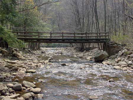
Figure 16—This bridge is on a side stream and in a flood plain. The backwater
effect during floods on the main stream has floated this bridge away twice.
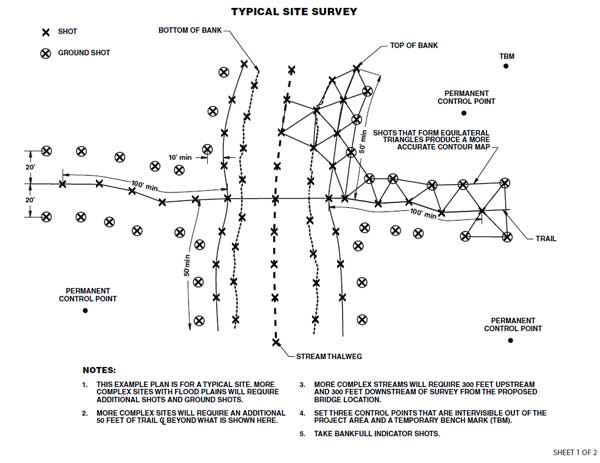
Figure 17—Typical survey points that should be taken to produce a quality topographic
map for
the trail bridge site.
For long description click here.
The amount of geotechnical investigation required varies depending on the site (figures 18 and 19). A geotechnical engineer should investigate the site for soil and bedrock conditions. An easy method used by the Forest Service is the Williamson Probe (Hall and others 2004). The probe works best when used in gravel or sand, which gives the operator an idea of the relative density of the sand and the depth of soft zones encountered. Borings are desirable for sites with unacceptable soils (unstable soils, clays, silts) or highly fractured sheer bedrock faces. Bedrock should be assessed for the degree of fracturing, gaps between the fractured surfaces, the material's hardness, and the degree to which it has weathered.
Wet and unstable sites and sites with clay and silt soils should be avoided, if at all possible. Unsuitable foundation material can cause structures to settle and fail. All major bridge sites should have a geotechnical study completed with at least one boring drilled for each abutment or pier. The type of bridge substructure is site specific and should be designed with the assistance of a geotechnical engineer (Davis 2001, Michigan Department of Transportation 2004).

