
Assembly Instructions
- Assembling the Rails
- Assembling the Jack Stands
- Attaching the Rails to the Jack Stand Assemblies
- Attaching the Center Rail Uprights
- Installing the Capstan Drive
- Installing the Overhead Trolley Cable Supports
- Placing the Cutter/Reel Assembly on the Rails
- Attaching the Master Control Panel
- Installing the Trolley System and Electrical Wires
- Installing the Capstan Cable
- Attaching the Debris Collection Bin
- Connecting the Voltage Transformer Box
- The Fully Assembled Top Pruner
The top pruner is modular for ease of transport. The cutter/reel assembly travels on two 8-foot, 6-inch-long 6061-T6 aluminum rail sections (figure 2) separated by a 4-foot, 6-inch center section. The sections are connected by side plates.

Figure 2—Connecting the rail sections.
A plastic insert is installed in the ends of the rail
sections so the rectangular tubing will not be crushed when
the spliced joint is bolted together with ¼-inch nuts, bolts,
and washers. The bolts fit tight in the bolt holes. Use a rubber
or plastic mallet and a long tapered or pin punch when
removing and installing bolts to reduce the chance of
damaging the bolt's threads. Tighten nuts to 40 inch-pounds.
Do not overtighten the nuts or you may crush the aluminum
tube, making it difficult to disassemble the rail system.
Lay out two jack stands at each end of the assembled rails (total of four jack stands). Attach the jack stand crossbar using 9/16-inch nuts, bolts, and washers (figure 3a). Attach two top plates to each jack stand. Use ¼-inch nuts, bolts, and washers (figure 3b).

Figure 3a—A jack stand assembly (two jack stands and a jack stand
crossbar).
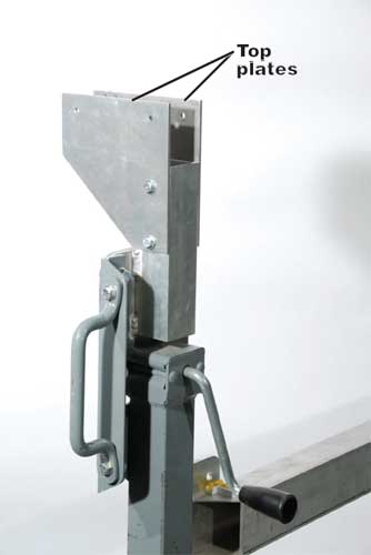
Figure 3b—Top plates attached to the top of a jack stand.
Attaching the Rails to the Jack Stand Assemblies
Once the rails and the jack stands are assembled, each end of the rails must be attached to the top of a jack stand assembly. The jack stand assembly with the center kill switch (figure 4a) attaches to the ends of the rails with the adjustment slots. Get the jack stand assemblies in about the correct position and stabilized so they don’t move. Lock the caster wheels!
Lift each rail assembly and place it between the jack stand assembly's top plates (see figure 4a). Install ¼-inch nuts, bolts, and washers. Ensure that each bolt is routed through the plastic insert so the rectangular aluminum tubing will not be crushed when the nuts are tightened. Use a long tapered or pin punch to help align the holes. Install the second jack stand assembly on the other end of the rails (figure 4b).

Figure 4a—Attach the rails to the jack stands after locking the caster
wheels.

Figure 4b—Both jack stand assemblies are attached to the rails.
Attaching the Center Rail Uprights
Attach the center rail uprights as shown in figures 5a and 5b with ¼-inch nuts, bolts, and washers. The "Authorized Personnel Only" sign must be installed on the inside of the center rail upright beside the overhead trolley system. The sign helps keep the trolley cars from snagging on the uprights.
If the rail stops (see figure 4a) haven't already been installed, install them now. Both stops are installed on the rail assembly that has the sign.

Figure 5a—Attach the uprights for the center crosspieces.
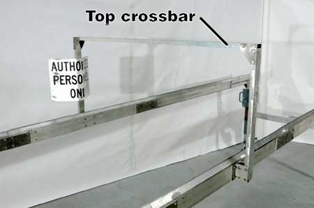
Figure 5b—Attach the top crossbar for the center rail uprights.
Install the capstan drive assembly as pictured (figure 6a); install the idler pulley on the opposite end, which has the adjustment slot (figure 6b). Use ¼-inch nuts, bolts, and washers. Be sure to install plastic inserts in the aluminum tubing so the tubing won't be crushed when the nuts are tightened.

Figure 6a—The capstan drive assembly.

Figure 6b—The idler pulley for the capstan drive.
Installing the Overhead Trolley Cable Supports
Install the trolley cable's vertical anchor on the end of the rail that has the adjustment slot (figure 7a). Plastic inserts are not needed because the bolts don't go through both sides of the rectangular tubing. Use ¼-inch nuts, bolts, and washers. Extra washers between the vertical anchor and rail provide the proper clearance from the top of the rail. The intermediate support rod is installed near the opposite end of the same rail (figure 7b). The trolley cable turnbuckle stays attached to the end of the rail.
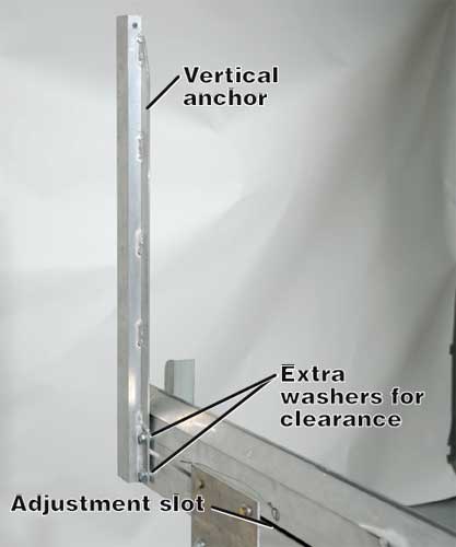
Figure 7a—The trolley cable vertical anchor.

Figure 7b—The trolley cable intermediate support rod and
trolley cable turnbuckle.
Placing the Cutter/Reel Assembly on the Rails
Two people are needed to lift the cutter/reel assembly (figure 8) safely onto the rail system. Make sure that the cutter/reel assembly rolls freely along the entire length of the rails.
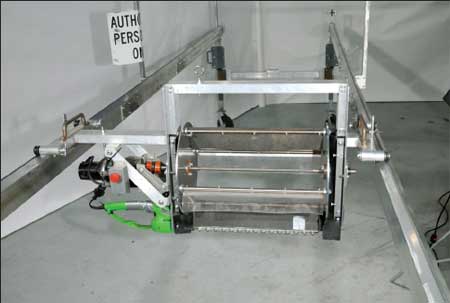
Figure 8—Two people are needed to place the cutter/reel assembly safely
on the top pruner's rails.
Attaching the Master Control Panel
The master control panel (figure 9) is modular. It hangs over the crossbar on the jack stand assembly that does not have the permanently mounted kill switch. It can be placed in any position along the rail as long as the operator can reach the controls—especially the kill switch—during the top pruning operation. Although the electrical boxes and connectors are waterproof, make sure that the panel's plastic splash guard is down to keep water off electrical components.

Figure 9—The master control panel hangs from the jack stand crossbar.
Installing the Trolley System and Electrical Wires
The trolley system suspends a five-strand electrical wire that runs from the cutter/reel assembly to the kill switch permanently mounted on the jack stand assembly. Another five-strand electrical wire runs from the master control panel alongside the rail with the trolley system to the same kill switch.
Attach the longer of the two five-strand electrical wires to the trolley cars while they are on the ground. Route the trolley cable (steel cable coated with plastic) through the trolley cars. Attach one end of the trolley cable to the vertical anchor (see figure 7a). Lift the cable with the trolley cars, attach it to the intermediate support rod and tighten the turnbuckle (figure 10a).

Figure 10a—The trolley cable with trolley cars and electrical cable.
The trolley cable does not have to be perfectly level. The electrical wire must not hang down so far that it could interfere with the cutter/reel assembly as it travels by. Attach the appropriate electrical connectors to the kill switch on the cutter/reel assembly and the kill switch permanently mounted on the jack stand assembly (figures 10b and 10c).

Figure 10b—The electrical connection at the cutter/reel assembly.

Figure 10c—Routing the electrical cable into the kill switch permanently
mounted on the jack stand assembly.
Figures 10d to 10i show the shorter of the two five-strand electrical wires that is routed from the kill switch permanently mounted on the jack stand assembly to the master control panel along the side of the rail that supports the trolley system. Figure 10j is an overall view of the wiring.
IMPORTANT! When making the final connections to the kill switch, master control box, and cutter/reel assembly, take a close look at the connectors. These special fittings can only be connected one way. To prevent damaging the pins, carefully match the pins to their mating sockets in the connectors.
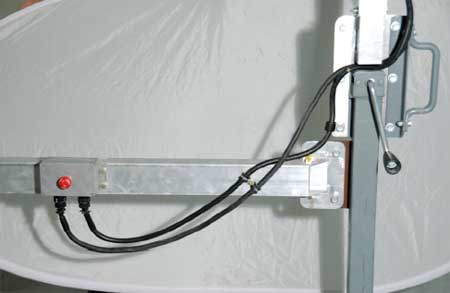
Figure 10d—Routing the electrical wires into the kill switch.

Figure 10e—The electrical cable and electrical wire are routed along the
end of the rail.

Figure 10f—The electrical wire is routed along the side of the rail.
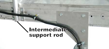
Figure 10g—The electrical wire is routed around the intermediate support
rod.
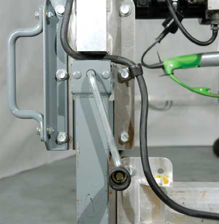
Figure 10h—The electric wire is routed above the crank handle on the
master control box end of the top pruner.

Figure 10i—The final routing of the electrical wire to the master control box.

Figure 10j—An overall view of the top pruner’s wiring without the voltage transformer.
Wrap the capstan cable around the capstan and the nylon idler pulley on the opposite end of the rail (figures 11a to 11c). Use 1½ turns of cable on the capstan. Secure the ends of the cable to the cutter/reel assembly as shown in figure 11c. Use the turnbuckle to take up slack in the cable. Do not overtighten the turnbuckle.

Figure 11a—Installing the capstan cable on the capstan.

Figure 11b—Installing the capstan cable on the idler pulley.

Figure 11c—The capstan cable connection at the cutter/reel assembly.
Attaching the Debris Collection Bin
Once the cutter/reel assembly is restrained by the capstan cable, attach the debris collection bin (figures 12a and 12b). Ensure that the bin is attached securely.

Figure 12a—Attaching the debris collection bin.

Figure 12b—The debris collection bin's quick attachment slots.
Connecting the Voltage Transformer Box
Connect the voltage transformer box (figures 13a and 13b) to the on/off switch on the master control panel. Plug the voltage transformer into a properly grounded 120-volt wall socket.
Ensure that the wall receptacle has a ground fault interrupter. The circuit breaker should be rated for at least 15 amperes.

Figure 13a—The voltage transformer.
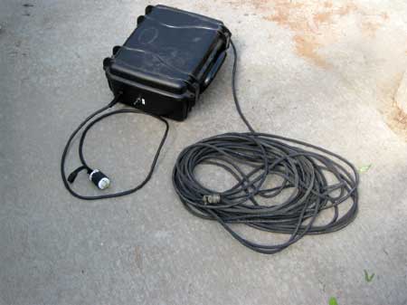
Figure 13b—The waterproof plastic voltage transformer box.
The Fully Assembled Top Pruner
The Lucky Peak greenhouse top pruner is now fully assembled (figure 14).

Figure 14—The fully assembled Lucky Peak greenhouse top pruner.