
Filing the Saw
Opinions vary among saw filers on the order of steps followed in filing a saw. Guidelines offered by saw companies differ significantly. After examining the reasons for the different orders, I prefer the following order:
- Cleaning—removing rust or pitch.
- Hammering—straightening a saw if it has bumps, kinks, or twists.
- Jointing—the means by which the tips of all the cutter teeth on the saw are made to conform to the circle of the saw.
- Raker fitting—includes shaping the raker gullet and swaging and sharpening the raker.
- Pointing up cutter teeth—sharpening the teeth by filing.
- Setting—bending the tips of the cutter teeth away from the plane of the saw, causing the kerf to be wider than the saw.
Tools necessary for:
- Hammering
- Two steel straightedges about 10 to 14 inches long.
- 3- to 4-pound cross-pein saw hammer (some manufacturers call them cross-face hammers).
- Fairly flat anvil.
- Jointing
- Jointer (short or long).
- 7- or 8-inch special crosscut file (mill bastard blunt file).
- Saw vise.
- Raker fitting
- 7- or 8-inch slim-taper (triangular) file.
- Pin gauge, raker gauge, or 8- to 16-ounce tinner's riveting hammer for swaging.
- 6-inch, slim-taper file with "safe" corners (corners ground smooth).
- 6-inch mill-bastard file.
- Saw vise.
- Pointing up cutter teeth
- 7- or 8-inch special crosscut file (mill bastard blunt file) for lance-tooth saws.
- 6- or 8-inch Great American crosscut file for championtooth saws.
- Saw vise.
- Setting
- 8-ounce set hammer (or tinner's riveting hammer).
- Setting stake or set tool, or anvil and spider.
- Saw vise.
Often a filer must clean a rusty or pitchy saw. One good method is to lay the saw on a flat surface and clean it with an ax stone or a pumice grill stone. Liberally douse the saw with a citrus-based solvent to dissolve the pitch and keep the stone from plugging up with debris. Small kinks show up as bright areas when they are high spots and dark areas when they are low spots. Use only enough pressure on the cutter teeth to clean them. If metal is taken off the tips, both set and tooth length will be affected.
Hammering or StraighteningFew saws are completely straight. Although slight kinks or bumps will not cause much trouble, a straight saw requires minimum set and is less likely to buckle during the push stroke when one person is sawing…and it will cut straighter.
The saw to be straightened is hung vertically from one of the handle holes.
Hold the straightedges lightly, one on each side of the saw, so they are directly opposite each other. By moving the straightedges back and forth, as well as along the saw, any kinks or bumps can be found. If you move the straightedges with a slight twisting motion, quite small kinks can be found by the difference in resistance to twisting the straightedges. A straightedge contacting the convex side of a kink will twist more easily than one on the concave side.

Locating kinks using two straightedges

Sawmaker's straightedges
When a kink is located, determine its shape and axis by moving the straightedges over its surface. Mark its shape with chalk or grease pencil (a wetted finger works well, too). Put the concave side down flat on the anvil, and with the appropriate face of your cross-pein hammer, strike the saw several times over the kink. (The appropriate face is the one that is fairly parallel to the kink axis). Check the kink with the straightedges and determine further action. Take care to strike the saw with the face of the hammer and not the edge. When hammering is done properly, the hammer should leave no visible mark. A slightly round-faced, 3-pound hammer can be used but results aren't as good as with a cross-pein hammer.

Hammering out a kink
If it is not possible to acquire a straightedge specifically for saw work, there are acceptable substitutes. A desirable straightedge will be light, stiff, and reasonably straight. A thickness from 0.050 to 0.100 inch is acceptable, but the thinner straightedge is better. Substitutes might be a draftsman's or machinist's straightedge, or the rule on a combination square.
JointingThe number and variety of jointers are considerable, but the principle is the same for all. They hold a file in such a way that the jointer can be run over the saw teeth to ensure the teeth all lie on the circle of the saw. There are short and long jointers. The short jointer, generally part of a combination saw tool, is by far the more common.
Jointer combination saw tools

Short Jointer
To use the short jointer, insert the file so it rests flat on the file supports (lugs) and adjust the screw so the file bends to conform to the circle of the saw. Make sure the surface of the file is square with the guide rails on the body of the jointer. The file may be warped or improperly seated on the supports. Insert the file so it runs in the normal filing direction. (If a file is used backward, its life will be severely shortened.) Because a new file often will cut faster than desired, a wornout 7- or 8-inch special crosscut file with the tang broken off works well.
Place the jointer on one end of the saw. Holding the jointer so the file rests on the cutter teeth, run the jointer the length of the saw using uniform downward pressure. This is important if the circle of the saw is to be maintained. It is also important to hold the guide rails on the body of the jointer in contact with the side of the saw at all times to ensure that the file is square to the saw.
After the jointer has been run the length of the saw, look at the teeth. If each tip has a shiny spot where the file has just touched it, jointing is complete. If some teeth are so short they weren't touched, repeat the process until all teeth show the mark of the file. If a tooth has been chipped or broken so it is much shorter than the rest, don't worry about it. No sense jointing the life out of a saw to make it perfect.
Jointing the cutter teeth

Long Jointer
If a long jointer is available, it achieves superior results and guarantees a round saw when used properly. A saw that has deviations from its arc (bumps or troughs) won't saw smoothly. The long jointer operates on the principle that three points in a plane uniquely define a circle (or arc), or that there is only one circle that will simultaneously pass through three given points in a plane.
The long jointer has two "shoes" about 12 inches apart with a file mounted between them. The file can be moved up and down relative to the two shoes. Whether the shoes or the file moves is immaterial. The two shoes and the file constitute the three points that define a circle. Only two long jointers were ever commercially manufactured. One, a Gibbs jointer, was marketed by Simonds Saw and Steel Co., and the other by E. C. Atkins and Co. The shoes on the Gibbs jointer move and the file on the Atkins moves.
As with the short jointer, it is a good idea to make sure the file is square with the guide rails on the body of the jointer. This can be checked with a small square.
Jointing a saw with a long jointer

With the saw in a stable position, preferably in a saw vise, place the jointer about in the center of the saw. Adjust the jointer so that both shoes and the file contact the saw and tighten the adjusting nuts. By moving the jointer along the saw and observing whether the jointer rocks on the file or has space between the file and the teeth, the high and low places can be observed easily. When the high and low spots are found, adjust the jointer so the file clears all but the higher spots. This is done by placing the jointer on a high spot and adjusting it so the file and shoes will contact the saw. These are important steps. If the initial jointer adjustment were made with the file over a relatively low spot and the saw jointed with that setting, it would be impossible to get the saw into round without taking excess material off the center teeth.
With the jointer adjusted on the saw, pass it lightly and evenly from one end of the saw to the other. The very end teeth should be jointed in this process. This means dropping one shoe or the other off the end of the saw to run the file over the end teeth. The file will cut the tips off the high teeth. If—as is often the case with really worn saws—the file will not make contact toward the end of the saw, the end teeth are too long. This can be corrected by jointing the ends more severely than the center of the saw. If the teeth are particularly long, a lot of time can be saved by cutting these teeth down with a handheld file, checking your progress periodically with the jointer.
As with the short jointer, the saw should only be jointed until all the teeth have been marked by the file (except extremely short or broken teeth). The less metal taken off the teeth, the less work the filer must do later in pointing up the teeth, and the longer the saw will last.
The end teeth of a solid-ended saw cannot be effectively jointed with a long jointer unless the solid section is filed to or below the circle of the saw.
It is possible to cut the solid end off a saw and repunch the holes for the handles.
Modifying a saw for jointing

- Fitting Straight Rakers
- Fitting Swaged Rakers
- Repairing Bent Rakers and Cutter Teeth
- Broken Raker Tip
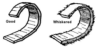
The raker teeth remove shavings that the cutter teeth have severed from the wood. For a saw to operate efficiently, the raker must remove all the wood severed by the cutter teeth, but no more. If too little wood is removed (too short a raker), energy will be wasted because of unnecessary friction between the cutter teeth and unremoved wood. If too much wood is removed (rakers too long), it is necessary for the raker to break the uncut fibers along the edge of the chip, resulting in wasted energy and a "whiskered" shaving.
Shaving
Because the cutting teeth exert pressure on the wood as they cut, a certain thickness of wood is compressed and springs back after the teeth pass over. As a result, fibers are not severed quite as deeply as the teeth penetrate. Consequently, the rakers following the cutter teeth must be shorter by the amount that the wood springs back, so no unsevered wood is removed. The amount of springback varies with wood type, moisture content, saw weight, and cutter tooth shape. Optimum raker depth depends on all these factors.
How a cutter tooth cuts

Optimum depth is obtained by experiment, but figures vary from 0.008 inch for hard or dry wood to 0.030 inch for soft, springy wood; 0.012 inch is a good average figure to begin with.
The depth of the rakers below the cutter teeth is determined by using a tool called a raker gauge or raker depth gauge.
The raker depth gauge is generally part of a combination saw filing tool of which numerous varieties were manufactured. The essential feature of all of them is a hardened steel filing plate with a slot cut in it a little wider than the thickness of a saw and a little longer than the distance between the two tips on a raker. This is held on a frame so that when the gauge is placed over the raker, the top of the filing plate is the same level as the desired raker depth. The raker tips are cut to the level of the plate with a file. The height of the filing plate is adjustable.
Raker Gauges

Morin raker gauge

Simonds precision saw tool

Anderson raker gauge
Adjustment of the depth gauge is straightforward. With the simpler gauges, such as the common Morin gauge, two screws hold the filing plate to the frame, and the adjustment is made by putting pieces of paper between the frame and the filing plate. The Simonds precision saw tool adjusts by sliding the filing plate up and down two ramps. A scale on the side of one of the ramps indicates the depth of the top of the filing plate. Each division of the scale corresponds to 0.004-inch difference in the height of the filing plate. A notch opposite the scale on the filing plate indicates the desired raker depth. The Anderson gauge adjusts by moving the plate up and down with a screw. Only minor adjustments should be made using the screw, because large deviations could break the brittle filing plate. Paper between the filing plate and the tool frame can be used for large adjustments. The Anderson gauge is the only known gauge with a sloped filing plate. Instead of filing the raker tip flat, it establishes a 15-degree clearance angle.
One way of checking the setting of a raker gauge is to file a raker using the gauge. Place a straightedge between the two cutter teeth on each side of the filed raker and measure the relative height with a feeler gauge placed between the raker and straightedge.
Filing raker teeth

There are two basic ways a raker can be shaped before it is filed to its proper depth using the raker depth gauge. These are known as straight (plain) and swaged rakers. There are advantages and disadvantages to each method. The straight raker is by far the easier to file, but it results in a relatively "slow" running saw. The swaged raker is considerably more difficult to shape, but the results are a superior running saw. The reason for the difference is apparent when one remembers that the raker acts like a chisel to remove the shaving. Much less energy is required to remove wood from a board if a chisel is held at a low angle to the board than if it is held vertically. Swaging results in a raker tip that is similar to a chisel held at a low angle to the wood.
Fitting Straight Rakers
The teeth of a saw are formed by punching, so the gullets of most saws are rough. With a 7- or 8-inch, slim-taper file, dress (smooth) the outside face of the rakers from the raker tip to the bottom of the sawdust gullet. Make sure the file is held square with the saw. This will provide clean, sound metal for the cutting edge of the raker, cause less friction between the outside face and the shaving, and aid shaving removal.
Next, file the raker to the proper depth. Place the properly adjusted raker gauge on the saw so the raker fits in the slot in the filing plate. Hold the gauge so it rests firmly against the tops of the cutter teeth as well as the side of the saw. Run a file across the raker tips until they are even with the top of the filing plate. Once the raker tips have been filed, the rakers must be sharpened. With a 7- or 8-inch slim-taper file, shape the raker gullet to the approximate shape (shown next), rounding the gullet out to the tip until the flat spot on the top almost disappears. If the tip is overfiled, it changes the raker depth. If not filed enough, the flat spot acts like a "sled runner" and does not allow the edge to work properly.
Shaping a raker tooth (straight
raker)

If you're using an Anderson-type gauge, this step is not critical. The clearance angle has been established and a good-sized "flat" spot can be left. Make sure the end of the filing slot in the Anderson gauge is held firmly against the tip of the raker. Otherwise, the raker tip will be filed too low.
Fitting Swaged Rakers
Swaging is forming the leading edge of the raker into a curve so it more efficiently picks up the shaving. It is done by striking a prepared raker tip on the inside face with a hammer to bend the tip outward in a smooth curve.
Tools necessary are a pin gauge, 8- to 16-ounce hammer for swaging (16-ounce hammer preferred), raker gauge, 6-inch, slim-taper file with "safe" corners, and a 6-inch, mill-bastard file. A pin gauge generally is part of a combination saw-filing tool.
I know of no hammers specifically designed for swaging. A swaging hammer should have a face small enough to allow you to strike the raker tip with the center of the hammer face. The best substitute for a swaging hammer appears to be a tinner's riveting hammer. A swaging hammer should weigh about 16 ounces. A lighter (8-ounce) hammer can be used, but a 1-pound hammer is easier to use.
Tools needed to fit swaged rakers

Combination saw-filing tool and pin gauge

Swaging hammers

To Prepare the Raker—File it approximately to the shape shown at right with the slim-taper file. The exact shape depends on whether the raker is straight or if it has been swaged before. The objective is to shape the tip so it can be bent without breaking but retain enough thickness to prevent bending during use. The cutting angle should be between 30 and 40 degrees.
Preparing a raker

The raker is now ready to be "swaged to the pin." This means bending the raker by striking the inside face of the raker tip with a hammer until the tip just clears a preset screw (called a pin) on a combination saw tool.
The pin is adjusted so the swaged raker is 0.002 to 0.003 inch higher than the finished raker depth. This is done by first filing a raker to depth using the raker gauge (which has already been set using methods described previously). Next, place the pin gauge over the raker and adjust the pin (screw) depth so a 0.002- or 0.003-inch feeler gauge will just pass between the raker tip and the pin. Check the clearance again after tightening the locknut.
Gauging rakers with the pin gauge
on the combination saw tool

To Swage a Raker—Strike the raker tip a square blow and check the height with the pin gauge. If it is still too high, continue alternately swaging and checking until the raker tooth just clears the pin. Keep an eye on the shape of the bend. The outside face of the raker should bend in a smooth arc. A kinked raker tip will be difficult to swage next time the saw is filed, and it will quite possibly break. If the tip begins to kink, the hammer probably is being used too high on the tip. If it won't bend, the tip may be too thick or the hammer is being used too low on the tip. Often in the case of a new saw or a used saw with straight rakers, it will be necessary to partially swage the tip. Thin the tip with the file and continue swaging.
There is no pat answer to the question: "At what angle is the raker struck?" This will vary with the shape of the raker tip and must be learned from experience. Keep an eye on the desired swage shape. Knowing where to strike the tip will come with experience.
Striking the inside face of the
raker tip with a hammer

Some saws are so hard and consequently brittle that there is a possibility of breaking raker tips when swaging. If a saw is so hard that a fairly new file keeps slipping while the filer is shaping the raker gullets, or if a raker actually breaks when being swaged, the rakers should be tempered.
To temper the raker, polish one side of each raker until it is shiny. Place the saw in a vise. Heat the top three-fourths of the tooth uniformly using a propane torch. As it gets hotter, the color will go from light straw to brown, to deep purple, to dark blue, to light blue, to a light yellow color. Opinions differ on how far to temper the rakers (or to heat them to what color). A compromise seems to be between light blue and the second yellow. A suggestion would be to first temper to light blue and if trouble is still experienced, temper again to the second light yellow. Don't heat into the body of the saw because it may cause the saw to warp. Be very careful about playing the torch flame on the raker tips—they heat very fast, making them extremely easy to overheat. The result is a soft raker that will bend in hardwood and will not hold an edge.
Once the rakers are "swaged to the pin," the tips are dressed on the outside face. To dress the swaged tip, a 6-inch, slim taper file with safe corners is passed lightly across the under edge of the swage to square it up and establish the rake angle. It is most important not to nick the raker with the edge of a file. A nick can cause the tip to break off during swaging or while the saw is being used. This is the reason for the ground safe corners on the dressing file. After dressing the outside face and rake angle, joint exactly as with the straight-style raker. As with straight rakers, a trial depth of 0.012 inch is good for average conditions.
The last step is to dress the sides of the rakers. The swaging process often widens the raker at the tip. This can be corrected by holding a 6-inch mill-bastard file flat against the raker and saw and making one or two light vertical strokes.
Dressing a raker

Repairing Bent Rakers and Cutter Teeth
To check for bent rakers, make up a spider (set gauge) for zero clearance on an unbent raker. A bent raker can be found easily by using the spider in the same manner as for checking cutter tooth set (see Setting).
To straighten a bent raker, the concave side of the raker is placed on an anvil and hammered until the tooth is straight. Badly bent cutter teeth could be straightened the same way.
Broken Raker Tip
A broken raker tip allows the other tip on the raker to bite too deeply on the cutting stroke, causing the saw to catch just as it does with a long raker. File the unbroken tip shorter, about 0.005 inch initially. If it still catches, continue filing.
Pointing Up Cutter TeethTo point up the cutter teeth, tilt the vise away from you at about a 45-degree angle. With the vise tilted, the flat spot on each tooth caused by jointing should appear bright. To accomplish this, place the main light source in front so you can see a good reflection from the flat spot. A wide set of windows (preferably without direct sunlight) works well. Two 4-foot fluorescent lights mounted end to end on a wall supply uniform lighting regardless of weather conditions. Avoid point sources of light such as incandescent bulbs and direct sunlight.
For filing the teeth, a 7- or 8-inch special crosscut file is used. The tooth shape illustrated below is good for general purposes.
A good general-purpose cutter
tooth

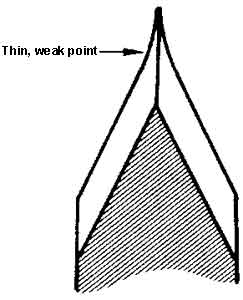
The stroke should be more nearly up and down than across the tooth. The main point to keep in mind when filing a cutter tooth is to file just enough to almost make the flat spot from the jointing operation disappear. Overfiling upsets the relationship between the cutters and the rakers and also results in a weak point. A slight rolling or rocking motion of the file generates a slightly convex filed surface and results in a more durable tooth. Because of the set, a tooth whose filed surface is flat will develop a concave cutting edge and a thin, weak point.
A poorly filed cutter tooth
The more pointed a tooth is filed, the deeper it will sink into the wood and the "hungrier" a saw will be. However, a sharply pointed tooth will wear faster than one less sharply pointed. The consensus is that there should be less bevel on a cutter tooth for hardwood than for softwood.
Tooth shapes

As the tooth is being filed, it is a good idea to periodically remove the burr that forms on the back side of the tooth, because the burr can obscure the true tooth shape. Remove the burr with a whetstone or a light stroke of the file across the tooth back—just enough to remove the burr. The back side of the tooth must not be filed, because it may cause the saw to bind. The burr also can be removed with a piece of hardwood.
Filing a cutter tooth

After all the teeth are filed, hold a fine stone flat against the saw. Pass it over the teeth to remove any residual burrs, especially at the tips of the teeth. A burr under the spider would cause an error in the tooth set.
SettingTo set a saw is to bend the tip of each cutter tooth a slight amount away from the plane of the saw. Just as alternate teeth are sharpened opposite each other, they are set opposite to each other. Setting helps prevent binding by cutting a kerf that is slightly wider than the saw. The amount of set required depends on the type of saw used and the type of wood being cut. A saw should be set only as much as required to keep it from binding. More set than necessary results in more work to make a wider kerf and a saw that flops in the cut with the possibility of a curving cut. The set required can vary from almost nothing for a crescent-taper-ground saw in dry hardwood to 0.030 inch for the same saw in soft, punky wood. A set of 0.010 inch is a good preliminary figure. Flat-ground saws require more set.
There are two basic methods of setting: spring setting and hammer setting. Spring setting is done by using a tool with a slot that fits over the top of the cutter tooth. The tip of the tooth is bent the required amount. This method is not recommended because of the possibility of bending the whole tooth and the fact that a tooth doesn't seem to hold a spring set well.
Spring set tool

There are several ways of hammer setting a saw, only one of which is recommended. Two other methods are briefly discussed for familiarity.
One method uses a setting stake. The setting stake is placed on a log or block and the wedge fully driven in to keep the stake in a firm position. The blade of the saw is laid on the stake with the point of the cutter tooth projecting over the bevel about ¼inch. The tooth is then struck with the set hammer as shown.
Using a setting stake on a stump

Another method uses a tool that is placed over the cutter tooth and is struck with a hammer.
Striking a cutter tooth with a
set hammer

Using a setting tool to set cutter
teeth

A third method uses a hand-held anvil and a hammer.
The principle is the same for the three methods: the tooth is bent over an anvil with a direct or indirect hammer blow.
The first two methods have definite disadvantages over the third. They each require a specialized tool, and they are slow. To check the set in the first method, the saw must be lifted off the setting stake.
The second method is a little more efficient because the saw doesn't have to be moved. The tool can be used with the saw in a vise. There is no chance of a misdirected hammer blow marring the tooth. However, there's a good chance of banging and dulling the tooth tip with the tool, and the tool isn't really designed for removing set if too much is put into the tooth.
The third method is recommended because of its speed and accuracy. Necessary tools are an 8-ounce set hammer, a set anvil, and a spider (set gauge).
There doesn't appear to be a current manufacturer for a hammer specifically designed for setting. A setting hammer should have a fairly small face. A large face such as most ballpein hammers have is difficult to use for setting without hitting adjacent teeth. The best substitute for a setting hammer is a tinner's riveting hammer that weighs about 8 ounces.
Anvils were manufactured in a variety of sizes and shapes. Most were made of hardened steel and had a bevel to bend the tooth over. There is no known manufacturer for hand-held anvils. Any piece of steel that can be held comfortably in the hand, has a flat face, and weighs about 2 pounds will work. A piece of 1½-inch-diameter shaft about 5 inches long works well. It is not necessary to have a bevel—simply set the tooth over the edge of the face.
The spider (set gauge) is used to measure the tooth set. To measure the set for which the spider is adjusted, place it on a flat surface so that the feet on the three short legs contact the surface. With light pressure on the three short legs, measure the clearance under the fourth foot (or longer leg) with a feeler gauge. A piece of plate glass or a mirror will work for the flat surface, though it is wise to check the spider several places on the surface so errors caused by irregularities can be averaged.
Spiders

As indicated earlier, a set of about 0.010 inch would probably be satisfactory for an average cut using a felling saw. About 0.015 inch of set is required for a heavy bucking saw.
The spider "set"

To adjust the spider for less set, place it on a flat carborundum stone, and while putting pressure on the short crosspiece, grind the feet down until it measures correctly. For more set, shorten either end of the long crosspiece. It is important that the foot at the end of the long leg is flat and parallel to the plane defined by the other three feet. This assures a constant reading no matter where the tip of the cutter tooth contacts the foot. This can be checked by lightly grinding that foot while the two feet on the short crosspiece are in contact with the stone and observing the resulting pattern on the foot.
To set the saw, place an anvil on the point side of the tooth and strike the tooth on the beveled side with a set hammer. The bevel on the anvil should be about ¼inch below the tip of the tooth and the direction and placement of the hammer blow such that the tip of the cutter tooth is bent over the bevel. Be sure to strike the tooth squarely. If the tooth is struck a glancing blow with the edge of the hammer face, the point of impact will be badly marred. This sometimes work-hardens the metal enough that a file won't cut it and it may make the tooth more susceptible to breaking.
Setting cutter teeth with hand-held
anvils

It is also important to keep the face of the anvil parallel to the plane of the saw during setting. If it is held at an angle, the tooth will be twisted after it has been set. Check the set with the spider. If the vertical legs rock, there is insufficient set and the procedure should be repeated. If the horizontal legs rock, there is too much set and some must be taken out. Move the anvil nearly to the top of the cutter tooth and strike a light blow.
Correcting an overset tooth

Setting cutter teeth

Sometimes a tooth will be bent from a point below the filed part of the tooth. This can be determined by checking with the spider up and down the tooth. If this is the case, place the anvil on the tooth just below the bend and straighten it by hammering the opposite side of the tooth just above the anvil.
