
|
Bob Simonson, Program Leader |
|
San Dimas Technology
& Development Center
444 E Bonita Ave
San Dimas, CA 91773
(909) 599-1267
SDTDC Home > Inventory & Monitoring
Williamson Drive Probe
The main problem with the original design of the Williamson Drive Probe is the transfer of shock load through the couplings. Threaded couplings are not meant to take a shock load. When a shock load is applied, the force is directed to the threads. This force loosens and weakens the coupling. The solution to this problem is to insert a spacer inside the coupling so that the two pieces of pipe come in direct contact with the spacer. This way the spacer transfers the load from pipe to pipe rather than the threads. A special spacer must be made for the first connection where the hammer directly contacts the coupling.
Couplings
- Threaded couplings need internal spacers so that the two pieces of pipe are in contact with each other. This is so that the force from the hammer blow is not absorbed by the threads, but transferred from pipe to pipe.
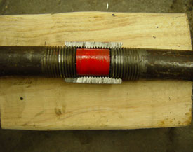
- Spacers can be made using commonly available 5/8" bolts, tubing or stock. Spacer must be cut down so that the two ends of the pipe come into contact with it once they are tightened on the coupler.
- Spacer must be placed between end cap and final pipe as well.
- Spacers must me custom made depending on the coupling used. Coupling length and thread engagement vary. Spacers must be made accordingly
First coupling
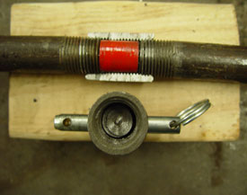
- In addition to the spacer, the threaded coupling must be bolted to the spacer so the energy from the hammer is transferred to the spacer.
- This can be achieved by drilling a hole through the spacer and coupling. Secure these two with a 3/8" grade 8 bolt or pin of similar strength.
Parts List
- Threaded merchant coupling
- Spacer inside merchant coupling
- Spacer can be made by cutting a 5/8" bolt or using hollow spacers commonly found in hardware stores
- Bolt or pin to connect spacer to first merchant coupling
- 3/8" bolt or pin
Measurements
- Find distance between pipes on inside of threaded coupling. Thread pipe into each end of coupling and mark each pipe at the edge of the coupling. Remove pipes and measure the length from the end of each pipe to the tape. Add lengths together and subtract from total length of coupling. (See Figures 1 and 2)
 |
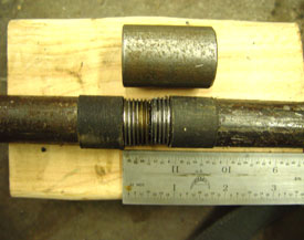 |
| Figure 1: Marking pipe to measure for spacer Click here for larger image |
Figure 2: Measuring for spacer length Click here for larger image. |
Fabrication
- Cut spacer to length measured in step above
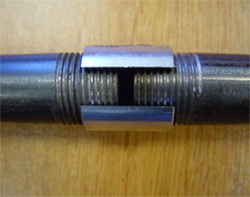
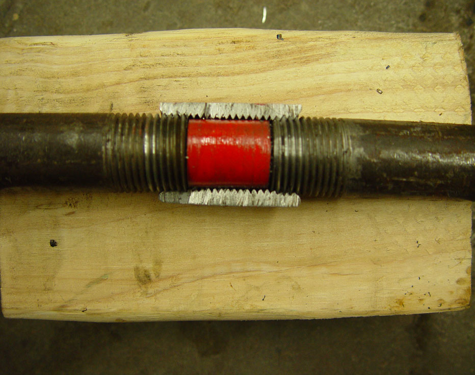
- Thread pipes into coupling until they bottom out on the spacer (See Fig. 3)
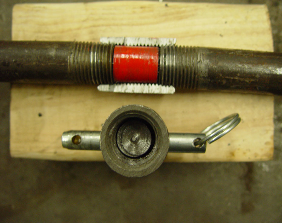
- In first coupling which receives the hammer blow, drill a 3/8" hole through coupling and spacer assembly.
- Install 3/8" diameter bolt or pin into hole drilled. (See Fig. 4)
 |
 |
| Figure 3: Cutaway of spacer assembly Click here for larger image. |
Figure 4: Example of first union. Click here for larger image. |
Correlation Data
