  Privacy
| Legal Privacy
| Legal |
Table of Contents Back | Next | Cover Page |
Technology & Development Center |
How to Conduct Static Tests of Aerial Retardant Delivery Systems
he test team maintains an inventory of equipment, including linear displacement transducers (floats), pressure transducers, door potentiometers, a turbine flow meter, battery packs, power converters, data acquisition hardware and software, laptop computers, and video equipment. Certified calibration of test equipment is performed by the manufacturer at recommended intervals. The float (figure 2) consists of a stainless steel rod with a sensor attached to the top. A floating steel ball with a hole through it travels along the length of the rod as it tracks the fluid level in the tank. Voltage output depends on the position of the ball along the length of the rod. The length and number of floats needed for a test depends on the tank's design. For example, if the tank has compartments with different geometries, each compartment will have to be instrumented. If the geometry of an individual compartment is not uniform, several floats may have to be mounted in the same compartment.

Figure 2—The proper length of the float
depends on the size of the tank.
A differential pressure transducer (figure 3) is used to measure negative pressure in the tank when it is being emptied. This transducer has two ports. The active port is exposed to the inside of the tank through a length of plastic hose. The reference port is exposed to atmospheric pressure. Voltage output depends on the differences in pressure between the two ports. Power input is regulated to keep the baseline output constant. Often, the plastic hose is moved to different tank locations during a test to check for pressure differences. Door potentiometers record door movements as the tank is being emptied. The potentiometers are mounted to a bracket, which is mounted on the tank so that the potentiometer shaft lines up with the door hinge. A stiff wire is attached to the potentiometer shaft and the door. As the door swings open, the wire turns the potentiometer shaft. Voltage output changes as the shaft rotates. Power input is regulated to keep baseline output constant. Video equipment may be used to measure door movement and operation rather than door potentiometers.

Figure 3—A hose must be attached from the
reference port to the aircraft's
exterior if
the tank relies on cabin air for venting.
A turbine flow meter and totalizer are used to calibrate the floats and to confirm the volume of the system being tested. The meter is placed inline with the loading hose. The totalizer converts meter output into gallons and provides an output of one pulse per gallon.
Gel-cell battery packs (12 volt) are the most reliable and simplest power sources for static test instruments. They are relatively light, compact, and rechargeable. Aircraft power may be used for test instruments but the current drawn by the instruments can interfere with the tank controller or the aircraft's electrical system. It is safer to use gel-cell battery packs.
Data acquisition hardware consists of a connection board, a laptop computer, and a PCMCIA card for the laptop computer. The connection board's terminal block connections provide a simple and versatile means of attaching wire leads from instruments (figure 4).
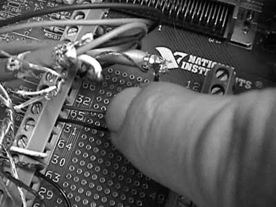
Figure 4—Instrument output connection board. MS-type (military specification)
connectors are needed for permanent instrument installations, but
connection boards with terminal block connections, such as the one shown,
are suitable for temporary static test installations.