  Privacy
| Legal Privacy
| Legal |
Table
of Contents Back | Next | Home | Cover Page |
Technology & Development Center |
Asphalt Paving of Treated Timber Bridge Decks
Traditionally, timber bridges were built with flexible beams and stiff decks. The solid beams were closely spaced and the nail-laminated decks were usually oversized. Glued-laminated timber allows fabrication of deeper, stiffer beams and uses thin, flexible glued-laminated deck panels.
Example 3—Seven bridges (figure 6) on the Wolf Creek Road in Lincoln County, MT, were constructed in 1969. The bridge superstructures are solid beams spaced 25 inches apart. The decks are nail-laminated two by sixes for a deck thickness of 5 3/4 inches. The beams are relatively flexible and the decks are very stiff. The bridges were paved with a cold-mix asphalt shortly after construction. The timber decks have occasional deteriorated laminations that would be logical slip planes for differential deflection, yet the 32-year-old bridges exhibit only random reflective cracking, which would be expected in pavement this old.

Figure 6—Bridge across Wolf Creek near
Libby, MT, showing minimal cracking.
Spacing beams closer together or using thicker decks can stiffen glued-laminated panel decks, preventing deflection-induced pavement cracking. However, such design changes increase the cost of a timber bridge.
A more effective solution is to mechanically interconnect the glued-laminated deck panels. The most common method, developed by the Forest Products Laboratory in 1971, uses steel dowels. This system is described in Timber Bridges: Design, Construction, Inspection, and Maintenance (Ritter 1990). A series of dowels are placed in predrilled holes at middepth of the sides of the glued-laminated panels. Design specifications are included in the Standard Specifications for Highway Bridges (American Association of State Highway and Transportation Officials 1996). This system can be complicated to construct because deck panels can be difficult to align and pull tightly together. The dowels must fit tightly enough to prevent movement. The predrilled holes in the timber deck panels should not be oversized by more than 1/16 inch.
Example 4—The Mill Creek Bridge near Medford, OR, was constructed in 1956. It is a three-span bridge initially designed with a transverse nail-laminated timber deck nailed to three glued-laminated timber beams spaced 5 feet 5 inches apart. In 1978, the nail-laminated timber deck was replaced with transverse glued-laminated timber deck panels lag-bolted to the beams. The deck panels were interconnected with steel dowels (figure 7). The deck was paved with asphalt pavement shortly after the deck panels were installed. The 22-year-old paving shows some reflective cracking over the deck panel joints. However, the cracks are intermittent and small and appeared gradually. The cracking may be caused, at least partially, by shrinkage of the individual deck panels. The deck is functioning well and shows no signs of further deterioration.
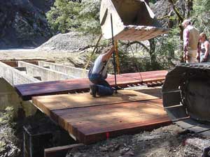
Figure 7—Dowel-inerconnected, transverse glued-laminated
deck panels on the Mill Creek Bridge near Medford, OR.
Another interconnection system-which may be easier to install and more economical-is a longitudinal stiffener beam (load distributor beam) attached to the underside of the deck midway between the longitudinal load-carrying beams. This stiffener beam should extend the length of the bridge and be continuous across at least three deck panels. The stiffener beams must have a minimum stiffness of 80,000 square kip-inches. They should be bolted through the deck near the edges of all glued-laminated panels (Weyerhauser, Inc. 1980).
Example 5—The Lighthouse Bridge across Upper Salt Creek in the northern end of the Olympic Peninsula in Clallum County, WA, was constructed in 1994. The 103-foot-long by 34-foot-wide double-lane bridge was constructed with full-length stiffener beams (figures 8 and 9) between the glued-laminated timber beams. The 6 3/4-inch glued-laminated timber deck is supported by glued-laminated beams spaced 5 feet apart. The asphalt pavement was laid down shortly after the glued-laminated timber deck panels were installed. No cracking (figure 10) had occurred when the bridge was inspected in October 1999. The deck panels are attached to the beams with steel 5- by 5- by 5/16-inch angle irons that also help stiffen the deck.

Figure 8—Deck stiffener beams installed under
transverse glued-laminated deck
panels on
the Lighthouse Bridge near Port Angeles, WA.
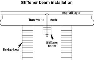
Figure 9—Stiffener beam between bridge beams.

Figure 10—Crack-free deck on the Lighthouse Bridge
near Port Angeles, WA.