  Privacy
| Legal Privacy
| Legal |
Back | Next | Home | Cover Page |
Technology & Development Center |
Camera With Altitude for Wilderness Site Monitoring
The monopod and hiking staff heads come with standard ¼-in camera stud mounts. Unscrew the wooden knob on top of the hiking staffs to reveal the ¼-in camera mounts. A machine shop can make a custom connector using 1¼-in-wide by ½-in-thick by 3-in-long aluminum stock (see MTDC drawing 1028-01). Place sticky-backed hook and loop fastener (Velcro) on the metal platform and on the back of the level (figure 4). Attach the level using the hook and loop fastener. Screw the monopod and hiking staff into the custom-made connector.

Figure 4—A custom-made connector with an attached level
joins the monopod
to the lower hiking staff.
Choose hiking staffs that come with a universal ¼-in stud camera mount and a steel hiking spike, preferably heavier hiking staffs, those weighing 16.5 oz or more. The Missoula Technology and Development Center tested the Tracks Sherlock staff by Cascade Designs. Hiking staffs come with a rubber hiking boot that covers a steel spike. Using the threaded steel spikes, two staffs can be connected with a 3/8-16 UNC, 4-in-long steel coupling hex nut (figure 5). If you extend both hiking staffs to their full length, the assembly may flex and become a bit unwieldy. In such a case, one person can hold the assembly and an assistant can monitor the portable LCD viewfinder and activate the camera's remote shutter release.
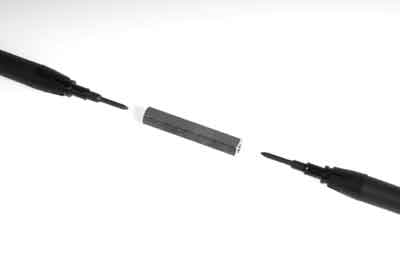
Figure 5—A hex nut couples the two hiking staffs.
The camera's tilt needs to be documented so photos can be replicated in the future. Download and print the 0- to 90-degree drawing (figure 6, available from MTDC) onto adhesive-backed 8½- by 11-in paper. Unscrew the Bogen No. B03232 camera tilt head handle and pull out the large bolt. Cut and apply the 0- to 90-degree sticker to both sides of the tilt head.
![[Drawing] 0- to 90- degree sticker to record camera's tilt angle.](images/fig06.gif)
Figure 6—The 0- to 90-degree sticker used
to record the camer's tilt
angel.
Assemble the tilt head and score a vertical line under the tilt head bolt (figure 7).

Figure 7—The Bogen tilt head with the 0- to
90-degree tilt sticker in place.