
Chapter 5— Designing Trail Crossings and Structures—Continued
Above-Grade Crossings
The design of above-grade crossings—bridges and overpasses—is complex and beyond the scope of this guide. Designing an appropriate above-grade crossing that meets the special needs of riders requires qualified and knowledgeable engineers, as well as other key resource specialists, who may include hydrologists, soil scientists, bridge and geotechnical engineers, and landscape architects. Design must comply with regulations established by the authorizing agency and Federal and State laws. Bridges require regular certified inspection according to governing regulations. Bridges on Forest Service lands, for example, must undergo inspection every 5 years.
Bridge and Overpass Design
Bridges and overpasses on horse trails require careful design to accommodate animal behavior. Horses and mules may hesitate if a bridge or overpass is narrow, sways, swings, vibrates, or is constructed of unfamiliar materials. Stock also are uncomfortable if the structure creates or amplifies noise. Even well-trained stock may balk at ramp approaches to bridges, especially where there are no approach rails. If a structure or tread appears dangerous, horses and mules usually refuse to go any farther. Incorporate skid-resistant surfaces and avoid designing steps on equestrian overpasses and bridges.
In general, there are six types of trail bridges:
- Cable bridges
- Deck girder/truss bridges
- Side girder/truss bridges—pony-truss bridges
- Arch bridges—deck or suspended bridges
- Miscellaneous single-unit bridges
- Covered bridges
Each bridge type and construction material has different span limitations that must be matched to site conditions. Longer crossings may have a very limited selection of suitable bridge types or materials. Prefabricated bridges, shipped in sections for reassembly on the site, may be appropriate for some situations. For example, the remote bridge shown in figure 5–17 consists of sections that were packed in and bolted into place. Engineering analysis is required for these products, along with strict adherence to the manufacturer’s installation and maintenance instructions.

Figure 5–17—This packable bridge comes
in 6-foot
sections that
are bolted together
at the site. Nearby cliffs encourage stock to
stay
on the tread, so approach rails are unnecessary.
A simple bridge (figure 5–18) is adequate for many stream crossings. Horse and pedestrian trails frequently cross suspension bridges (figure 5–19). Long or swaying suspension bridges (figure 5–20) can be daunting to stock and riders that are not accustomed to crossing them.
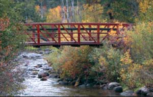
Figure 5–18—The weathered steel and
wood of this sturdy stock
bridge fit the setting.

Figure 5–19—This wood suspension bridge
is designed for
packstock use in a wildland
setting. The design would be
appropriate for
other users in other settings.

Figure 5–20—Inexperienced stock—and some
people—may
hesitate before crossing this
suspension bridge over the Colorado
River.
Resource Roundup
Crossing the Bridge
For more information regarding bridges and overpasses:
- A Guide to Fiber-Reinforced Polymer Trail
Bridges (Groenier and others 2006) is available
at http://www.fs.fed.us/t-d/pubs/htmlpubs/htm06232824. This Web site requires a
username and password. (Username: t-d,
Password: t-d)
- Guide Specifications for Design of Pedestrian
Bridges, 1st Edition (AASHTO 1997) is
available from the bookstore at https://bookstore.transportation.org/item_details.aspx?ID=37.
- Guide for the Development of Bicycle Facilities (AASHTO 1999) is available at http://www.communitymobility.org/pdf/aashto.pdf.
- Standard Specifications for Highway Bridges (AASHTO 1996) is available from the
bookstore at https://bookstore.transportation.org/item_details.aspx?ID=51.
- Transportation Structures Handbook
FSH 7709.56b (U.S. Department of
Agriculture, Forest Service 2005c)
is available at http://www.fs.fed.us/cgi-bin/Directives/get_dirs/fsh?7709.56b.
- Trail Bridge Catalog (Eriksson 2000) is available at http://www.fs.fed.us/eng/bridges.
Bridge Site Selection
Bridges with the horizontal alignment perpendicular to the stream are the shortest and usually the least costly to build. Avoid sharp and blind curves on the immediate approaches to bridges, because curves adversely affect sight distance. The vertical alignment—or grade—of bridges also affects sight distance, drainage, and footing. Adjusting the trail alignment to address these issues usually costs less than modifying the bridge.
Bridge Grade
Bridges with a slight grade or camber shed water better than flat bridges. However, grades that are too steep can cause footing problems. Bridge grades on trails should not be greater than any part of the trail itself and when possible, should not exceed 5 percent. Camber on arch bridges also should not exceed 5 percent. Figure 5–21 shows a trail bridge with camber.

Figure 5–21—For safety, the camber on
equestrian bridges should
not exceed 5 percent.
Bridge Width
The minimum suggested bridge width on horse trails in areas with low levels of development is 5 feet (1.5 meters). In areas with high levels of development, 12 feet (3.6 meters) is preferred. Bridges in areas with moderate levels of development often range between 5 and 8 feet (1.5 and 2.4 meters) wide. Bridges that are wider than 6 feet (1.8 meters) and narrower than 10 feet (3 meters) are only suitable for riding single file, but riders may be tempted to pass or ride two abreast, a potential source of conflict. For facilities subject to the AASHTO guidelines, match the clear bridge width to the width of the shared-use trails that lead up to them. Then add an additional 2 feet (0.6 meter) on each side (AASHTO 1999). This extra width gives all trail users the minimum horizontal shy distance from the railing or barrier. It also provides maneuvering space when trail users encounter others who have stopped.
Trail Talk
Bridging Streams and Ditches
The British Horse Society (2005b) prefers bridges that are 6.6 feet (2 meters) wide for streams and ditches in the United Kingdom. The organization recommends a bridge width of 13.1 feet (4 meters) when the river measures at least 26.2 feet (8 meters) across. They also advise consulting with highway engineers for site-specific requirements.
Bridge Load Limits
Bridges, causeways, and boardwalks on horse trails must meet engineering specifications to support the weight of a large group of stock. Structures designed primarily for pedestrians and bicycles are not strong enough for horses and mules, because the decking cannot withstand the force of horseshoes or the point load per hoof. In addition, bridges must be engineered to withstand the vibration caused by single or multiple animals. Stock, including their riders or loads, usually weigh from 1,000 to 1,700 pounds (454 to 771 kilograms).
Trail Talk
Mule Maneuvers
Suspension Bridges for Mountain Warfare (U.S. War Department 1944) provided specifications for suspension bridges with spans of up to 400 feet (122 meters). These bridges were used to carry light loads over long gaps. The War Department required standard military suspension footbridges to carry three packmules, each with a handler, spaced onethird of the span length apart. Light equipment bridges were designed to carry seven mules and handlers, spaced at intervals of one-seventh the span length. Intervals are crucial for figuring a structure's load capacity and fundamental frequency.
Design bridge beams and stringers for the anticipated maximum loading or load combinations, including live loads, snow, wind, snow groomers, earthquakes, and light vehicles. Covered bridges in snow country have additional load considerations.
Resource Roundup
Live Loads
Live loads for hikers, ATVs, motorcycles, bicycles, snowmobiles, and stock or packstrings are grouped together as pedestrian live loads. When designing bridges, consult the live load, deflection, and small load criteria outlined in the Guide Specifications for Design of Pedestrian Bridges, 1st Edition (AASHTO 1997), or other applicable sources. The guide is available from the bookstore at https://bookstore.transportation.org/item_details.aspx?ID=37.
Bridge and Overpass Structural Materials
Select materials for bridges and overpasses based on durability as well as for strength, esthetics, cost, and appropriate level of development. Common bridge materials include timber, steel, concrete, and fiberglass. Many companies have engineered plans for standard bridge lengths of wood, steel, and fiberglass. Table 5–1 shows suggested structural materials suitable for different levels of trail development. Esthetics and the setting—wildland, rural, urban—also affect choices.
Bridge and Overpass Surface Materials
Select surface treatments for bridges and wetland structures carefully. Most stock will hesitate to step from the tread to the bridge unless the transition between tread and bridge is as smooth and uninterrupted as possible. The surface of the tread and bridge should be flush and have similar colors. A step up or down to the bridge draws the trail animal's attention to the change in material.
Common bridge decking materials include wood, concrete, steel grates, fiberglass, and composites made from plastic and wood. Wood decking can be planks or glue-laminated panels. Because wood surfaces may be slippery when wet, they work best in areas that don't get a lot of rain. Concrete bridges surfaced with appropriate natural soils, sand, crushed rock, or a rough surface generally are horse friendly. Avoid steel grates because stock may be frightened when they look through the grate or hear a horseshoe striking it. Fiberglass decks must have a wearing surface that can withstand the impact of horseshoes. The surface of plastic laminates can be slick, requiring that they be manufactured with a roughened surface. Avoid decks that sound hollow when stock travel across them.
Bridge wearing surface refers to a temporary layer of decking that is easily replaced when worn. Often less expensive, untreated wood is used for this purpose. The wearing surface frequently is the same width as the trail on each end and tapers to a narrower width toward the center (figure 5–22). This gradual reduction in width serves to funnel trail traffic to the center of the bridge tread. This pattern is less costly than providing a wearing surface that extends the full bridge width for the entire span length.
In areas with low levels of development, the Forest Service often constructs decking from wood planks that are 3 inches (76 millimeters) thick if no wearing surface is included. When used along with wearing surfaces, the decking consists of transverse wood planks 2 inches thick by at least 8 inches (51 by 203 millimeters) wide, placed on the bridge stringers. The wearing surface consists of longitudinal planks 2 inches thick by 12 inches (51 by 305 millimeters) wide. Horse loads normally are concentrated loads. Horse loads determine the thickness of bridge decking and wearing surfaces. Pedestrian live loads are uniform loads over the entire deck. Pedestrian live loads determine the size of bridge stringers.
Select tread surface materials that don't become slick from use, particularly if the bridge has any slope. Timber cleats, rubber matting, or other wearing surfaces can be installed to improve traction.

Figure 5–22—Wearing surfaces are a
relatively easy
and economical
way
to prolong the life of bridge decking. The
tapered pattern guides
stock to the
wearing
surface
in the center of the bridge.
Bridge and Overpass Sides and Railings
Trail bridges require railings, except in certain circumstances. Trail bridges that don't have railings must have longitudinal edging, commonly called curbing or curbs. Before constructing bridge curbs instead of railings, agencies may require documentation that substantiates the decision. For example, if an analysis shows that the potential hazards along the trail are the same or greater than the hazards of a bridge without a railing, curbs may be used in place of railings. The Forest Service requires an engineering analysis to determine whether the hazards along the trail are the same or greater than those on a bridge without a railing. In general, trail users in rural and urban settings are more likely to be small children or less experienced adults who will need a railing. In wildland settings, trail users normally are more experienced and railings may be unnecessary.
The first consideration in selecting railings must be safety. According to the Trail Bridge Catalog (Eriksson 2000), guidelines for rail systems fall under the following:
- Building Code—Railings on trail bridges in urban
settings must meet building code requirements,
such as the International Building Code (IBC).
These railings are designed for pedestrians, not
riders, and must have vertical balusters that are not
easy to climb. The code requires a handrail at least
42 inches (1.067 meters) high that does not allow a
4-inch (101.6-millimeter) sphere to pass through.
- AASHTO Code—Horizontal railings on trail
bridges frequently used by children must meet
AASHTO Standard Specifications for Highway
Bridges. A 6-inch (152.4-millimeter) sphere must
not pass through the railing in the bottom 27
inches (685.8 millimeters), and an 8-inch (203.2-
millimeter) sphere must not pass through the area
higher than 27 inches (685.8 millimeters). The
code also requires a handrail at least 54 inches
(1,372 millimeters) high for equestrian traffic.
- Remote Areas—Railings on remote trail bridges must be at least 54 inches (1,372 millimeters) high for equestrian traffic. The handrail system also must have one or more intermediate rails so that the vertical distance between rails does not exceed 15 inches (381 millimeters). The Forest Service requires handrail systems on bridges to have at least two horizontal rails above the tread level.
Table 5–2 gives selected design criteria for Forest Service bridges on horse trails. Live load pressures for hikers, ATVs, motorcycles, bicycles, snowmobiles, stock, or packstrings are grouped together under pedestrian live loads.
Other considerations may justify railings or barriers. For example, horses and mules may become frightened if they can see high-speed vehicles or other distractions passing beneath or near the bridge. Provide a solid barrier or panel topped with an open-view railing (see figures 3–18 and 5–23). Use a similar design on the bridge approach to ease the transition from the trail onto the bridge deck. Such panels on approaches guide a reluctant trail animal onto the bridge. Construct the panels on one or both sides to extend a distance appropriate to site conditions. Angle the extensions outward from the bridge structure to form approach rails (figure 5–24).

Figure 5–23—A solid barrier topped with an
open view railing
is often more acceptable to
horses and mules than an open view
fence
alone. This open view railing is on the Marjorie
Harris Carr
Cross Florida Greenway Land Bridge.
Figures 5–27 and 5–28
show additional views
of the
land bridge.

Figure 5–24—Approach rails guide stock onto
a bridge. Large
rocks or other natural objects
sometimes
are used to block
alternate routes.
Railings should be free of protrusions that can catch on legs, feet, stirrups, or tack. Install all connecting hardware with the smooth side toward the trail user.
Horse Sense
Rubbing the Right Way
Some shared-use bridges incorporate an optional rub rail—a smooth, flat panel that is attached to the inside of the railing (figure 5–25). Rub rails keep bridge users or their gear from catching bridge members. Make sure the rails have no edges or gaps that can snag reins, ropes, people, or stock.

Figure 5–25—Wood rub rails are frequently used
on bridges to
keep saddles, backpacks, bicycle
handlebars, and other equipment
from
snagging on posts.
Bridge Clearance
Safety is compromised when riders are forced into areas with narrow or low clearance. Construct bridges with a minimum overhead clearance of 10 feet (3 meters) in the equestrian trail corridor. The preferred overhead clearance is 12 feet (3.6 meters). Pedestrian and bicycle bridges over freeways frequently have vertical curved fences or roofs to prevent anything being thrown from the bridge. Tread location and inadequate trail clearance (horizontal or overhead) should not force riders to the center of the corridor or make it difficult for riders to pass stopped users safely. Loud traffic noises on these bridges may make them questionable for equestrian use.
Trail Talk
Low Down
The British Horse Society (2005b) advises building new road underpasses that have a vertical clearance of 12 feet (3.6 meters). If that is not possible, the minimum clearance is 11 feet (3.4 meters). The preferred width is 16.5 feet (5 meters) and the minimum width is 10 feet (3 meters).
Figure 5–26 illustrates a shared-use bridge for nonmotorized travel over a freeway. It has a separate, 12-foot- (3.6-meter-) wide equestrian tread in the center of the bridge where the vertical clearance is greatest. Pedestrians, bicyclists and other nonmotorized users use the separate treads on either side of the horse tread.

Figure 5–26—Separation barriers on this
shared-use bridge are
short
enough
for horses and mules to see over, so stock are
more
comfortable. The roof over the equestrian tread
(center) has a high
overhead clearance to
accommodate equestrians.
Horse Sense
To Dismount or Not?
Asking riders to dismount for trails or structures with low or narrow clearance is not recommended. Dismounting can lead to dangerous situations because riders have less control of a nervous or aggressive trail animal from the ground than when they're in the saddle. Dismounted riders risk being run over by a spooked animal. Occasionally, low clearance, narrow passages, or trail obstacles are unavoidable. In all cases, safety is the determining factor when deciding whether to require riders to dismount. Some riders are not able to dismount or remount on a trail without stepping up on something. If passages don't have adequate vertical or horizontal clearance for mounted riders, or if other considerations warrant leading an animal, warn riders with signs and provide mounting blocks at both ends of the obstacle. Consult Chapter 7—Planning Recreation Sites for more information regarding mounting blocks and ramps.
Bridge Sight Distance
Sight distance can be restricted by a bridge's arc or because approaches are placed at a poor angle. A long sight distance on bridges allows riders to see problems in advance, preferably the entire length of the bridge, plus approaches. When sight distance or visibility on bridges is limited, work with bridge and traffic engineers to determine proper remedial action. In urban and rural areas, this may include installing signs and signals.
Trails on Bridges and Overpasses With Traffic
Many stock are unfamiliar with bridges that also have vehicle traffic. The speed of the traffic on the bridge, noise level, and vibrations can make some stock nervous. Occasionally, managers designate a bridge for equestrians only. For bridges where motorized use is very low, if budgets and bridge conditions permit, separate riders from vehicles and other trail users. Where feasible, bridge design can incorporate barriers between two or more treads to separate riders and slow motorized traffic. The barrier would be subject to careful analysis and regulatory approval.
It is best if bridges over high-speed roads separate stock and traffic. Some shared bridges route traffic on one level and trail users on a different—usually lower—level. The traffic is not visible to the animal, and the sound of traffic is contained in the separate corridor.
Specialty Bridges
Several specialty land bridges over major roads in the United States have grass and shrubs planted in a soil-covered deck. Many user groups appreciate this design, which is costly. Figures 5–27 and 5–28 show the Marjorie Harris Carr Cross Florida Greenway Land Bridge over Interstate 75 just south of Ocala, FL.

Figure 5–27—The Marjorie Harris Carr Cross
Florida
Greenway
Land Bridge across
Interstate Highway 75 south of Ocala
allows
riders, hikers, and bicyclists to cross six
lanes of traffic. The
bridge is 52.5 feet wide
and 200 feet long.

Figure 5–28—Native vegetation in irrigated
planters on the
land bridge buffer users from
the sight of traffic below. Natural
surfaces
enhance the trail experience.
Below-Grade Crossings—Culverts and Underpasses
In some cases, underpasses—or below-grade crossings—are more suitable than at-grade crossings or bridges. Large-diameter structures—culverts and underpasses—generally serve riders well. Prefabricated underpasses are available in aluminum, steel, and concrete. They can be round, elliptical, arched, or box-shaped. Examples of underpasses are shown in figures 5–29 and 5–30. Trails with belowgrade crossings must meet design regulations or guidance such as AASHTO specifications, and they require the expertise of engineers. The advantage to recreationists and wildlife can sometimes justify the higher cost of below-grade crossings rather than at-grade crossings. When designing belowgrade crossings, carefully consider the safety of approaches, drainage structures, the tread surface, clearance, sight distance, and lighting. Figure 5–31 shows separate, adjacent underpasses for motorized traffic and trail users.

Figure 5–29—Underpasses can
have different
configurations,
such as this one with approach
wings.
—Courtesy of Bridgetek.

Figure 5–30—Make horizontal
trail clearance
in underpasses the
same width as the trail or
wider.
—Courtesy of Bridgetek.

Figure 5–31—For safety, provide separate
underpass routes for
motorized users
and trail users.
—Courtesy of Bridgetek.
Below-Grade Approaches
It is often difficult to provide the necessary overhead clearance required by riders when approaches slope down into below-grade passages. Design new structures so approaches are level with the trail tread. If drainage or site conditions require a slight slope, make it constant from one end of the passage to the other. Retrofitted below-grade trail approaches sometimes slope downward at both ends, reducing clearance and making drainage difficult. Avoid this situation wherever possible. When sloped approaches to retrofitted culverts or underpasses are unavoidable, design them with no more than a 5-percent grade. Avoid hard, smooth tread treatments for approaches.
Below-Grade Tread Surfaces
Relatively level, natural tread surfaces leading into underpasses generally require no additional treatment. The exception is a tread surface that is frequently wet or muddy. Sloping trails that are frequently wet may benefit from geosynthetic materials. If culverts don't drain adequately, they are unsuitable for horse trails. Design the approach and surfaces of the underpass to prevent water, snow, sand, soil, or other materials from collecting where they will hamper traction or interfere with clearance. Use horse-friendly surface materials. Make sure that the below-grade crossings are large enough for the equipment needed to maintain them. See Chapter 6—Choosing Horse-Friendly Surface Materials for more information.
Below-Grade Clearance
If a trail animal startles while in an underpass or below-grade culvert, the animal, rider, and other trail users may be injured. This is especially true in narrow underpasses or those with low, curved ceilings. For safety, design culverts and underpasses on horse trails so the vertical clearance is no lower than 10 feet (3 meters) across the entire width of the tread. The preferred height is 12 feet (3.6 meters). Horizontal clearance often extends 2 to 3 feet (0.6 to 0.9 meter) beyond the tread edge on both sides of the trail. Horizontal and vertical clearance in passages should be no less than the clearing limits on the rest of the trail.
When figuring horizontal and vertical clearance in underpasses, allow space for maneuvering and passing. Box-shaped structures should meet the standard height guidelines and be no less than 8 feet (2.4 meters) wide. A preferred width of 12 feet (3.6 meters) allows space for trail users to pass. The culvert in figure 5–32 appears wide enough for riders, but the vertical clearance is suspect. Culverts that curve near the top must provide 10 to 12 feet (3 to 3.6 meters) of overhead clearance without forcing riders to the center of the trail. Riders can suffer severe injuries if they hit their heads. The horizontal clearance at head height should be at least as wide as the trail itself and no narrower than 5 feet (1.5 meters) wide. This may be difficult to achieve with tapered culverts (figure 5–33).

Figure 5–32—When selecting equestrian
underpasses,
such as this
common
box culvert, carefully consider overhead
and horizontal
clearance.
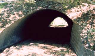
Figure 5–33—Riders need more lateral
clearance near the top
of underpasses than other
users. Provide 12 feet of overhead
clearance
that is the entire width of the trail. Avoid
sloping roofs
that force riders to the center
of the tread.
Enclosed-Area Lighting
Adequate lighting and sight distance are important inside, outside, and at approaches to enclosed trail corridors. The eyes of stock don't adjust quickly to lighting changes, and many animals stop or hesitate when they can't see well.
In highly developed areas, artificial lights may be helpful, especially if the corridor approach is sloped. If possible, install fixtures flush with the approach walls. In trail corridors, locate fixtures at least 10 feet (3 meters) above the trail surface where they will not encroach on clearance. Keep the scale appropriate to trail users, and vary the light intensity for trail conditions or location. Consult a professional lighting designer or engineer for a site-specific plan.
Some divided highways provide a light well—or opening—in the median to allow sunlight into the passage below and enhance visibility during the day.
Trail Talk
Light on the Subject
Night travel often occurs on shared-use trails, which may suggest the need for lights. The Guide for the Development of Bicycle Facilities (AASHTO 1999) suggests maintaining average horizontal illumination levels of between 5 and 22 lux for trails, highway intersections, and in underpasses or tunnels. Higher levels may be advisable if security is an issue.
Culverts That Carry Water
With careful design, some culverts that carry water
can include a separate trail tread
(figure 5–34).
Successful designs prevent trail tread material from being eroded at either end of the culvert.

Figure 5–34—A culvert shared by a stream and the
trail. When flooding
occurs, both courses channel floodwater.
Figure 5–35 illustrates a culvert that carries water and also includes a trail. Inside the culvert, a channel along the outer edge of the trail carries water out of the culvert. Abutments direct the water to a catchment pond below the trail tread.

Figure 5–35—A trail and a water channel share this specially
designed culvert.
The channel keeps water off the trail and
abutments direct the runoff into a catchment pond.