
Stowing the Canopy in the Container
- All directions (right, left, top, and bottom) are referenced from a jumper wearing the parachute lying face down, head toward the canopy. When you are done stowing the canopy and closing the container, the pack should look like figure 31.
- Place the skirt of the canopy and slider in the bottom left-hand corner of the container with the diaper locking stows on top. Position the remainder of the line stows so they face the inside of the container (figure 32).

Figure 31—Packed FS-14R parachute and container.

Figure 32—Position the skirt in the bottom left corner
of the container.
- Make one S-fold in front of the line stows filling the bottom corners of the container evenly (figure 33).
- Make a second S-fold from left to right in front of the first fold, filling both the top left and right corners (figure 34).
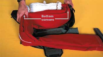
Figure 33—The first S-fold fills the bottom corners.

Figure 34— The second S-fold fills the top left and right corners.
- Fold the remainder of the canopy in flat accordion folds across the top of all the previous folds. Make the first flat accordion fold from the top right corner to the bottom left corner of the container (figure 35a). Alternate the folds so they evenly fill both the top and bottom corners of each side of the container (figure 35b).
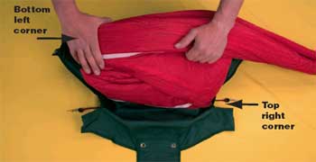
Figure 35a—Make the first flat accordion fold from the top right
corner to the
bottom left corner of the container.

Figure 35b—Flat accordion folds on top of all previous folds.
- Fold the apex under the last fold far enough to cover all of the vent lines (figure 36).

Figure 36—Fold the apex under the last fold to cover all vent lines.
- S-fold the pilot chute bridle on the center of the top fold. Take care to ensure the bridle is not twisted (figure 37).
- Place the chute on top of the pilot chute bridle with the soft cones parallel to the grommets on the container's top and bottom flaps (figure 38).
- Route the left pullup cord through the left grommet on the bottom container flap. Repeat with the right pullup cord. Lock the soft cones with temporary pins (figure 39).

Figure 37—S-fold the pilot chute bridle on the center of the top fold.

Figure 38—The pilot chute shown on top of the bridle and canopy.

Figure 39—Route the pullup cords through bottom flap grommets.
- Route the left pullup cord through the left grommet of the top container flap and lock the soft cone with a temporary pin. Repeat with the right pullup cord (figure 40).

Figure 40—Route the pullup cords through top flap grommets.
- Remove the pilot chute locking rod (figure 41).
- Route the left pullup cord through the grommet on the left side flap and lock the soft cone with a temporary pin. Repeat the procedure with the right pullup cord (figure 42).
- Pull the left pullup cord. Remove the left temporary pin from the soft cone. Insert the left curved ripcord pin of the ripcord handle into the soft cone. Pull the right pullup cord. Remove the right temporary pin from the soft cone. Insert the right curved ripcord pin of the ripcord handle into the soft cone. Match the Velcro on the handle with the corresponding Velcro on the container (figure 43).

Figure 41—Remove the pilot chute locking rod.

Figure 42—Close the side flaps.

Figure 43—Insert the curved ripcord pins on the ripcord handle.
- Rotate the pullup cords under the curved ripcord pins. Slowly remove the cords from the soft cone loops, taking care to avoid friction burns that will damage the soft cones (figure 44).

Figure 44—Rotate the pullup cords under the curved
ripcord pins, then remove them.
- Dress the container with a packing paddle. Fill out the packing data card and install the reserve knife in the pocket on top of the container. Check to see that both safety pins are attached to the reserve snaps (figure 45).

Figure 45—The reserve container after final dressing.
- Install the safety seal (figure 46).

Figure 46—Installing the safety seal.
Additional single copies of this document may be ordered from:
USDA Forest Service, Missoula Technology and Development Center
5785 Hwy. 10 West
Missoula, MT 59808–9361
Phone: 406–329–3978
Fax: 406–329–3719
E-mail: wo_mtdc_pubs@fs.fed.us
For additional technical information, contact John Kovalicky at MTDC:
Phone: 406–329–1015
Fax: 406–329–3719
E-mail: jkovalicky@fs.fed.us
Electronic copies of MTDC's documents are available on the Internet at:
http://www.fs.fed.us/t-d
Forest Service and Bureau of Land Management employees can
search a more complete collection of MTDC’s documents, CDs,
DVDs, and videos on their internal computer networks at:
http://fsweb.mtdc.wo.fs.fed.us/search/