
Appendix B—Installation Guide for Porous Pavement Panels as Trail-Hardening Materials for Off-Highway Vehicle Trails
The following discussion provides information on methods of installing GeoBlock and SolGrid porous pavement panels based on the author's experience in Alaska during the 1996, 2000, 2001, and 2002 summer field seasons.
Preplanning—The size of individual porous pavement panels (19 by 39 inches) lends them to constructing trail in 4.8-, 6.5-, and 8-foot-wide configurations (see figure B1 for panel layout configurations).

Figure B1—Typical panel layouts. For long description click here.
Table B1 provides information for ordering material, based on typical installation configurations.
| PANELS | Dollars per square foot | Dollars per panel | Square feet per panel | Panels per pallet | Square feet per pallet | |
|---|---|---|---|---|---|---|
| GeoBlock, 2 inch | 2.15 | 11.57 | 5.38 | 44 | 236.72 | |
| SolGrid | 1.53 | 7.83 | 5.12 | 78 | 399.36 | |
| PANELS | Linear feet per pallet at 4.8 feet wide | Dollars per linear foot at 4.8 feet wide | Linear feet per pallet at 6.4 feet wide | Dollars per linear foot at 6.4 feet wide | Linear feet per pallet at 8 feet wide | Dollars per linear foot at 8 feet wide |
| GeoBlock, 2 inch | 49.11 | 10.37 | 36.87 | 13.81 | 29.48 | 17.27 |
| SolGrid | 83.20 | 7.34 | 62.40 | 9.79 | 49.92 | 12.23 |
| 18 panels per 20 linear feet at 4.8 feet wide • 24 panels per 19 linear feet at 6.4 feet wide • 30 panels per 19 linear feet at 8 feet wide | ||||||
| UNDERLAYMENT | Dollars per square foot | Dollars per roll | Roll size in feet | Linear feet per roll, 4.8 feet wide | Linear feet per roll, 6.4 feet wide | Linear feet per roll, 8 feet wide |
| Polynet PN-3000 | 0.32 | 1,527 | 14.4 x 300 | 600 | 600 | 450 |
| Geogrid, Tensar 1100 | 0.25 | 540 | 13.1 x 164 | 328 | 328 | 164 |
| Geogrid, Tensar 1200 | 0.40 | 854 | 13.1 x 164 | 328 | 328 | 164 |
| Nonwoven geotextile 4545, 4-ounce | 0.06 | 265 | 12.5 x 360 | 720 | 640 | 540 |
| Nonwoven geotextile 4551, 6-ounce | 0.08 | 360 | 15 x 300 | 600 | 560 | 500 |
| Nonwoven geotextile 4553, 8-ounce | 0.08 | 360 | 15 x 300 | 600 | 560 | 500 |
| SCREWS | 14 screws per linear foot for 4.8 feet wide 18 screws per linear foot for 6.4 feet wide 28 screws per linear foot for 8 feet wide |
|||||
| CABLE TIES | About 100 ties per 100 feet of trail | |||||
| GRAVEL | Requires 1 cubic yard of gravel per 14 linear feet at 4.8 feet wide Requires 1 cubic yard of gravel per 10.5 linear feet at 6.4 feet wide Requires 1 cubic yard of gravel per 8.5 linear feet at 8 feet wide |
|||||
A typical installation requires the following:
Supplies
¾- to 1-inch No. 8 or 10 Phillips-head screws, galvanized or stainless steel (No. 8, 1-inch truss-head screws are generally the least expensive.)
Quik Drive screws (TRSD34S) 2,500 screws per box (for use with Quik Drive system)
Zip ties, 11-inch, 120-pound test (Catamount L-11-120-0-C or equivalent)
One ½-inch sheet of CDX plywood to help join panel sections (cut down to 24 inches wide and 1 foot longer than the installation width)
¾-inch CDX or all-weather plywood for joints (cut into 8-inch-wide strips the width of the installation)
One 2 by 4 by 8 piece of lumber
One 2 by 6 by 8 piece of lumber
Equipment
At least two 400 cc or larger ATVs for transporting workers and equipment
At least one flatbed or large-box ATV trailer for hauling panels
At least one small-tub ATV trailer for hauling equipment and supplies
Miscellaneous straps and tiedowns for trailers
5-gallon gas can
Chain saw with chain oil and mix gas, or a portable circular saw for cutting panels
Gas-powered weed trimmer with blade option
Shovels, pulaskis, and rakes
At least three portable drill drivers with extra battery packs (18 volts recommended)
One Quik Drive automatic screw gun (modified No. PHD18R with head for ¾- to 1-inch screws)
Utility knife
Leatherman tool for clearing screw jams
Tool belts, knee pads, drill holsters, and waterproof tool storage containers
100-meter tape measure, lath, flagging, marker pens
First-aid kit, communications equipment, water, sunscreen, insect repellent, rain gear, and similar items
Labor
Calculate 3 to 6 hours per 100 square feet for onsite installation. The actual time will depend on site conditions, logistics, and installation design.
Ideal crew size, two to four teams of three; one supervisor, one runner
Here is an example of the supplies and labor needed for a 4,800-square-foot installation, 6.5 feet wide by 800 feet long:
About 850 GeoBlock panels
About 140 SolGrid panels
Four boxes of Quik Drive screws (TRSD34S, 2,500 screwsper box)
2,000 screws
1,500 zip ties Catamount, L-11-120-0-C
5 days labor with an eight-person crew
Supplemental geotextiles and membranes are required in some locations to increase the flotation of installations in extremely muddy conditions, to support installations over long expanses of weak ground, or to help contain fill material. Table B2 lists the most commonly used materials and their purpose.
| Type of material | Application |
|---|---|
| Open-cell drainage mat | Reduces size of openings, increases flotation on extremely muddy sites |
| Nonwoven separation fabric | Eliminates openings, provides separation layer when filling cells |
| Geogrid | Provides lateral support of panels across ponded areas |
The author has used Polynet PN-3000 (or equivalent) as a suitable open-cell drainage mat. It decreases the size of openings to less than ¼ inch and also reduces the total opening by roughly 30 percent. This increases the flotation of the panels on extremely muddy sites and still allows for vegetation regrowth. A nonwoven separation fabric in an 8-ounce material weight can be used to completely eliminate openings when flotation needs to be maximized. Nonwoven fabric delays vegetation regrowth unless cells are filled with a growth medium. Vegetation regrowth helps anchor and stabilize the installation, integrate it into the environment, and improve site productivity. Tensar BX 1100 (or equivalent) has been used as a geogrid under-layment for installations longer than 100 feet in ponded areas. The geogrid provides a lateral membrane that helps prevent joint failure. Because the panels are neutrally buoyant and will float just below the surface in pooled areas, they should be filled with aggregate as a ballast when the trail crosses long ponded sections. A separation fabric should be used to contain the ballast gravel within the cells. In many cases, cells do not have to be filled because the grid cell provides an adequate traffic surface for most applications. Fill can increase regrowth in some cases, help integrate the installation, and provide a buffer for thermal contraction and expansion of the panels. High-quality fill is not required because the cell walls carry the load. Any readily available growth medium can be used. Gravel fill may also be necessary where tracked vehicles or snow machines with cleats will operate on panel surfaces. The gravel will help protect the soft plastic grid cell walls from crushing and abrasion.
Site Preparation—New trail locations should be cleared of trees, shrubs, rocks, and large tree roots. Tussocks and thick clumps of grass should be sheared off at ground level. It is generally not necessary to strip the site to mineral soil because vegetation growth through the open cells is desirable. For existing trails, the surface should be leveled to the extent practicable and center humps between wheel tracks and along trail edges should be roughly level to the depth of wheel ruts. Potholes should be filled to the extent that is practical. The installations handle variations in terrain along the course of the trail better than across the trail. An undulating surface is okay, but there shouldn't be more than a 4-inch variation across the surface. The smoother and more nearly level the surface, the cleaner the installation will look and the better the panels will be able to transfer load from one to another. Simple handtools such as shovels and grubbing tools (such as pulaskis) can be used for site preparation. Small backhoes, bulldozers, and/or tillers and weed trimmers may have application at some sites.
Staging—After the pallets of panels have been delivered to the trailhead, they can be broken down and shuttled to the staging areas with ATVs and small ATV trailers. Using double-axle ATV trailers to haul larger loads will increase the efficiency of shuttle operations and minimize trail impacts between the trailhead and staging areas. Machines that are 400 cc or larger are recommended for these operations.
Staging areas should be located along the identified alignment every 500 feet or so. Trail conditions may require that the trail be hardened before heavy loads can be shuttled to distant staging areas. If so, only stage enough panels to construct trail to the next staging area. Stock the staging areas as the trail extends to them. The staging areas should be relatively level and large enough to accommodate stacked panels and assembly areas. An area 20 by 30 feet is usually adequate. If a helicopter will be used to stage the panels, be sure to site the staging areas with clear approaches and leave extra room for drop zones.
Subsection Assembly—It helps to assemble panels into subsections before installing them. Stack panels neatly to the outside of the trail corridor, leaving room to assemble subsections on the trail side of the staging area. With the GeoBlock panels upside down on a flat, level surface, assemble the panels (refer to figure B1 for the panel layout configurations). For a 4.8- or 6.5-foot-wide trail, six panels will form a subunit. For an 8-foot-wide trail, 10 panels will form a subunit. Assembling the panels upside down places the edge tabs closer to the surface, making it easier to screw the panels together.
Either screw the panels together using individual screws or use a automatic-feed screw gun. A Quik Drive No. PHD18R (figure B2) with Quik Drive ¾-inch TRSD34S screw strips has been used successfully in Alaska. The Quik Drive gun has limited capability to countersink screws, so the panels must be upside down when using this tool. The tool must be slightly modified to allow it to countersink an additional 1/8 inch. To do this, grind off the small raised area on the base collar to increase the depth of drive. Screws should be driven through the center of the overlapping tabs between panels (figure B3). It is not usually necessary to place screws in every tab, but tabs should be fastened in adjacent pairs to pin the panels. At a minimum, a pair of tabs should be fastened on each side of a joint and along the outside edge. Along interior joints, screw a pair of tabs together along every 6 inches of the panel's length.

Figure B2—The Quik Drive automatic-feed
screw gun speeds assembly of the panel
subsections.

Figure B3—Illustration of the tab-fastening
screw pattern at panel joints.
Subsections should be assembled on top of each other so that the underlying panels provide a pattern for consistent assembly and a smooth and level base for constructing subsections. Repeat the same panel pattern with each successive layer (figure B4).

Figure B4—Assembling the subsections with
the Quik Drive drill system. Using this tool and
a standard 18-volt cordless drill, two people can
assemble 32 six-panel subsections in 1 ½ hours.
In the background, a worker drags a three-section
assembly along an installed trail segment.
Three-Section Assembly—Once a good stock of subsections is stockpiled, they can be assembled into three-section units. On an adjacent smooth surface, join three of the subsections together. Leave them upside down and use the same screw pattern along the joint as in the subsection assembly. Make sure that the subsections are oriented so that the panel pattern repeats itself in the proper sequence. This should be automatic if the subsections are placed in the same orientation as they were constructed. Again, assemble the three-section units one section on top of another until all the available subsections have been assembled into full three-section units.
Expansion Sections—Because unfilled GeoBlock panels tend to expand and contract under changing temperatures (up to 12 inches per 100 feet were documented in Alaska with a temperature variation of -20 °F to 90 °F), expansion sections are required whenever installations longer than 40 feet are placed in an exposed location. This includes areas where the panels are to be placed directly on soil or vegetation that is not shaded by overhead vegetation, where the panels are not ballasted with gravel or filled with soil, and sites where vegetation regrowth cannot be expected to provide adequate shading during the first year of installation.
To construct the expansion sections, assemble sections of SolGrid panels the same width as the GeoBlock subsections. The SolGrid panels interconnect with a slot and tab joint system (figure B5). Carefully lay out the panels so all of the tabs are aligned along the leading and right edges. This will take a few minutes to work out. Carefully repeat the pattern with subsequent sections. Lock the joints together with screws by screwing through the panel sidewall in the cell between the tabs. Stockpile enough SolGrid subsections to place one between every third three-section GeoBlock units (about every 40 feet).
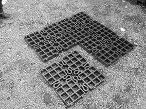
Figure B5—Two SolGrid panels. Note the slot
and tab fasteners along the edges and the
intergrated U-shaped expansion components.
Trail Panel Layout—Any required underlayment should be placed along the trail alignment before skidding the assembled panels into place. This may include a drainage net, nonwoven geotextile, and/or geogrid. Once those materials (if any) are in place, the assembled three-section units are flipped over and skidded into place. Temporarily place a 2-foot-wide piece of ½-inch CDX plywood at the joint to help the tabs along the joint match (figure B6). Starting at one edge, "zip" the tabs into place. One worker at the far end of the new section can assist by shifting the panel from one side to another and applying pressure as required.
Figure B6—A ½-inch sheet of CDX plywood
should be placed at section joints to provide
a flat surface to help join the panels.
Once the panels match, they are fastened together through the overlapping tabs from the top, using a standard cordless drill gun with a 2 ½-inch-long No. 2 Phillips bit (figure B7).

Figure B7—Joining the sections using a
screw gun. Note the underlying plywood.
Additional assembled sections are then skidded into place and fastened. More screws and cable ties are used to reinforce panel joints along the outside edges and anywhere additional strain might be encountered, such as areas where the terrain is irregular. Cable ties may also used to connect panels to the underlying Polynet.
Expansion Joint Connections—Expansion joint sections are fitted between every third three-section GeoBlock section. Because the SolGrid panels do not provide the same degree of load transfer as the GeoBlock panels, a geotextile underlayment such as Polynet or a geogrid should be placed beneath the expansion joint section extending 1 to 2 feet beneath the adjoining GeoBlock sections.
Trim the end tabs of the GeoBlock and SolGrid panels where the panel sections join. Butt the panel sections together and screw the panels together through the cell sidewalls. Screw from both sides to secure the joint. Use cable ties to further reinforce the joint.
An alternative expansion joint can be provided by leaving a 3- to 4-inch space between three-section assemblies. An 8- to 12-inch-wide piece of ¾-inch plywood can be attached under one panel edge and allowed to slide under the other panel if the gap needs to be reinforced.
Facilitating Curves—The size and configuration of the panels do not lend themselves to the construction of smooth radius curves. Curves must be facilitated with angular turns (figure B8). Fortunately, a wide range of angles can be constructed.

Figure B8—Angular cuts in the panel sections
help form the turns in the trail.
Angles are constructed by overlapping full three-section assemblies. The end edge tabs of the lower panel are trimmed off with a chain saw or other cutting tool. The overlying panel section is laid over the end of the first section and is carefully aligned in the new trail direction. A 2 by 4 is placed between the two panels to provide clearance for the saw blade, and the top panel is cut off parallel with the joint. A chain saw or other cutting tool can easily make the cut. Be careful not to cut into any screws! Eleven-inch-long, 120-pound-test zip ties (Catamount L-11-120-0-C or equivalent) are used to join the panel edges. Then place an 8-inch-wide strip of ¾-inch CDX plywood equally beneath each panel edge and screw through the base plate to further secure the joint (figure B9).

Figure B9—Corner joint showing cut, underlying
plywood, and cable ties. Note the screws through
the panel's plastic baseplate that secure
the panels to the plywood.
Finish—Use cable ties to connect panels to underlying Polynet or geogrid geotextile about every 3 feet along both sides of the installation. Place fill in cells as available or specified. No other anchoring is required.
Maintenance and Monitoring—Inspect the installation on a regular basis during the first season of use and annually thereafter. Reinforce joints with screws and cable ties as necessary. If joints separate, place an 8-inch-wide strip of ¾-inch CDX plywood beneath them and secure with screws through the baseplate. If joints buckle and overlap, install a thermal expansion joint at an appropriate spacing.
Material Sources
GeoBlock:
Presto Products Co.
Geosystem Products
P.O. Box 2399
Appleton, WI 54913–2399
Phone: 800–548–3424 or 920–738–1118
Fax: 920–738–1222
E-mail: info@prestogeo.com
Web site: http://www.prestogeo.com
SolGrid:
Sol Plastics, LP
1501 des Futailles Str.
Montreal, PQ, Canada HIN3P1
Phone: 888–SOL–PLAS or 514–254–8525
Fax: 514–254–6325
Ecogrid:
Pro-Seal Products, Inc.
16541 Redmond Way, Suite C
Redmond, WA 98052–4463
Phone: 800–349–7325
Fax: 425–821–1006
Web site: http://www.prosealproducts.com
Polynet and geogrid:
Any geotextile supply business