
Structures Requiring Foundations
Corduroy, turnpikes, causeways, and improved drainage are all constructed directly on the ground and do not require a foundation. The remaining techniques—puncheon, bog bridges, gadbury, and boardwalks—all require some sort of constructed foundation to raise the structure off the ground.
The type of foundation needed varies with the structure being constructed, materials available, and the site-specific soil and water conditions. More than one type of foundation may be appropriate for each structure, so we will discuss foundations first. These foundations include sleepers, cribbing, end-bearing piles, friction piles, and helical piles.
Sleepers (Sills)
The simplest foundation is to rest the tread plank or stringers on sleepers, also called sills, or mud sills. A log of a naturally decay-resistant wood or a large-diameter treated pole or post is used for the sleepers. Sleepers are used to support puncheon, gadbury, and bog bridge construction. The notching for each type of structure is different and will be discussed later in this chapter.
A sleeper (figure 24) is placed in a shallow trench at a right angle to the trail centerline. A second sleeper is placed in another trench parallel with the first sleeper. The distance between the two sleepers is the span. The span is determined with the help of someone with carpentry or structural engineering experience.
Pinning the sleepers to the ground with 24- to 30-inch driftpins is extra work, but it may reduce future maintenance in wetlands subject to flooding. Pinning is most important near streams or rivers where high water velocities may occur during flooding. Pinning may also reduce maintenance in areas of frequent slack-water flooding. The outer driftpins should be driven in holes drilled at opposing angles. Driftpins installed at these angles will resist flotation and uplift from frost and will also deter vandalism. If rebar is used for pinning, the hole can be 1/16-inch smaller diameter than the rebar. Otherwise, the hole should be the diameter of the pin.

Figure 24—Place sleepers in a shallow trench and pin them at
opposing
angles so they won't float away during seasonal flooding.
Timbers are sometimes used instead of logs for sleepers. Timbers are easier to work with because they do not require notching. However, timbers do not have the same rustic quality as logs. Precast concrete parking bumpers and other precast concrete units have been used for sleepers, but they are far from rustic. Concrete bumpers weighing 150 pounds per cubic foot are difficult to bring to the site. In most wetland soils, they will eventually sink into the ground.
Sometimes the base for the sleeper can be strengthened by excavating deeper, wider, and longer; laying down geotextile; adding several inches of gravel on top of the geotextile; and folding the geotextile back over the top of the gravel to encapsulate it. Lay the sleeper on top of this foundation.
Cribbing
In hummocky terrain or when crossing a wide, low area, log or timber cribbing can be used to support a trail. Usually logs are used to construct cribbing (figure 25). Dig two parallel shallow trenches a few feet apart. Place a sleeper in each trench and diagonally pin it to the ground with three 30-inch driftpins. Drive the outer two pins at opposing angles. Depending on the width of the completed trail, the first layer (or course) may be 3- to 5-foot-long logs. A second course of two more logs is placed on the first course of logs, near their ends. Each course of logs is placed at right angles to the course below and spiked or pinned to it. The cribbing is built up until the proper height is reached. Lay the top course perpendicular to the centerline of the trail. Stringers or plank can either be nailed to each of the top logs or timbers, or a single, large-diameter log can be notched and pinned to the top logs (similar to the sleepers described earlier).

Figure 25—Log cribbing with two sleepers.
If you use logs, saddle notches may be used in the bottom of all but the sleepers. This will result in a solid wall of logs. A simpler technique is to use a square notch at the ends of each log that contacts another. This technique will leave a 3- to 6-inch gap between the logs (figure 26).
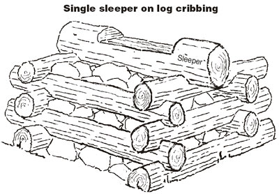
Figure 26—Log cribbing with a single sleeper. Do not
notch logs that
contact the ground.
Drive spikes or 12-inch-long driftpins into predrilled holes at the corners of the cribbing to hold it together. Avoid stacking the joints on top of each other. The joints must be offset or the driftpins from each course will hit the driftpins in the logs of the course below.
Timbers are easier to use than logs because they do not have to be notched. For greater stability and to prevent the cribbing from being washed away in floods, you can fill the open space in the core of the cribbing with stone.
Wire gabion baskets filled with rock also can be used for crib structures. Sleepers are placed on top.
Wooden Piles
Piles are another foundation technique. Three types of piles have been used for wetland trails. Structural engineers refer to these piles as end-bearing piles, friction piles, and helical piles (figure 27). Geotechnical engineers use a hand-operated relative density probe to help determine soil conditions. The probe is driven into the ground with a fixed force, allowing resistance to be calculated.

Figure 27—Friction and end-bearing piles. The pile in the middle
began as a friction pile but became an end-bearing pile because it
met solid resistance before fetching up.
End-Bearing Piles
End-bearing piles are used at locations where firm earth or solid rock is found 2 to 10 feet below the ground. Although the soil at these sites may support sleepers, piles can be used to support the tread at abrupt changes in grade when the tread must be 1 to 5 feet above the ground or water. Piles can also support handrails.
To place an end-bearing pile, excavate a hole a little wider than the pile to a point below the frostline. If you encounter solid rock in the bottom of the hole before reaching the frostline, the pile can rest on the rock. Power augers help make digging easier and faster. In wilderness areas or where only a few holes are needed, a posthole digger, manually operated auger, or shovel will do the job.
Place the pile upright and plumb in the hole. Place the excavated earth (or imported coarse sand or gravel) in the hole in 6- to 8-inch layers, equally on all sides of the pile, and compact it by tamping. A tamping bar is the best tool for compacting earth (figure 28).

Figure 28—A crowbar (rock bar) and a tamping bar. The tamping bar
is lighter than the crowbar and is best suited for loosening soil in holes
and for tamping around posts.
End-bearing piles can be made from naturally decay-resistant or pressure-treated wood, steel, or concrete cast in sonotubes (disposable cylindrical forms). Wood is typically used because it is readily available and easier to use than steel or concrete. Connections to a wood pile are also much easier to make, and the tools needed for the job are lighter and more readily available. Timbers are the first choice for end-bearing piles because their flat, squared sides are easier to connect to than the round surface of logs. Usually, rough-sawn, pressure-treated 6 by 6s are adequate for this work (figure 29).

Figure 29—Using squared timbers for end-bearing piles makes
connections easier than when round piles are used. Cut the tops at
an angle so they will shed water.
Friction Piles
Friction piles are normally used when the ground is wet and sloppy—areas where you need logs or some kind of a deck to stand on while you work. Friction piles for trail work are usually at least 12 feet long and 10 to 12 inches in diameter. Friction piles are considerably heavier, more awkward to transport, and more difficult to install than end-bearing piles.
A friction pile should be a naturally decay-resistant log or a pressure-treated log or pole. Cut a point on the narrow end and dig a shallow hole where the pile is to go. The pile must be driven with the wide butt end up and the narrow end down. The pile should stand as plumb as possible.
For backcountry wetland trail construction, friction piles are driven by hand. Pile driving is done with a "hammer"—a 2½- foot piece of 12-inch-diameter steel pipe (figure 30). A cap is welded at the top and two ½-inch-diameter holes are cut in the cap to let air out. Two steel handles of ½-inch-diameter reinforcing bars are welded to the sides of the pipe. At one area where friction pile construction was common, two of these hammers were used to drive the piles by hand. One hammer weighed 90 pounds and the other 135 pounds. Using these tools builds strong bodies. Usually two persons work together when operating these manual pile drivers.
The theory of the friction pile is that the surface of the pile develops friction against the sloppy soil. The deeper the pile is driven, the more friction develops, until finally the pile "fetches up" and can be driven only fractions of an inch with each blow of the hammer. When that point is reached, pile driving stops, normally at depths of 6 to 10 feet. Sometimes firm soil or rock will be reached before the pile fetches up. At this point the driving stops and the pile becomes an end-bearing pile.
If the trail is being built progressively, 12- to 16-foot piles can be driven by a small, lightweight machine with a pile driver attachment. Building a wetland trail strong enough to support the pile driver may be worthwhile in coastal areas that are subject to hurricanes, northeasters, or typhoons. If the wetland trail can support the machine, it will probably withstand some severe storms. If longer piles are needed, a much heavier pile driver can be brought to some sites on a barge.

Figure 30—A pile driver (hammer) can
weigh 135 pounds or more.
Bent Construction
Whether wood end-bearing or friction piles are used, once a pile is in place, the construction is similar. A second pile is placed on the opposite side of the trail centerline so that each is the same distance from the centerline. When both piles are in place, they are connected by one or two ledgers. The combination of ledgers and piles is called a bent.
On a one-ledger bent, the top of each wood pile is cut flat and level with the opposite pile. A 3 by 6 or 3 by 8 timber is placed flat on the top of both piles so that it extends a few inches beyond each of them. This timber, or ledger, is spiked to the top of each pile (figure 31).
When two ledgers are used, one is bolted to the front and one to the back of each pile, spanning the space between the piles. Drill a hole through each pile parallel with the trail centerline. These holes (and ledgers) should be level with each other. A 3- by 6-inch ledger is held in place on one side of the pile, and the hole in the pile is extended through the ledger. This is repeated until each ledger can be bolted to each pile. The ledgers should be level and level with each other.

Figure 31—A bent with one ledger. Spike the ledger to the top of
each pile. The pile and ledger are collectively called a bent.
Another method for the same type of installation is to determine the proper height of the ledgers and clamp the pair of ledgers to each pile of the bent. Drill a hole through the ledger, the pile, and the opposite ledger, all at once. This is faster, but requires two large clamps that can open at least 1 foot (figure 32).

Figure 32—A bent with two ledgers. Trim the tops of the piles at an
angle so they will shed water. The bolts go through the pile and both
ledgers.
After installing a pair of bents, pressure-treated 3- by 12-inch tread planks are nailed to the ledger or ledgers as described for the bog bridge on sleepers. If the planks are more than 2 feet above the ground or water, the tread should be at least two planks wide for trails that do not have to meet accessibility standards. Collect and dispose of treated wood trimmings and sawdust.
Where the deck will be more than 3 feet above the ground, diagonal bracing is needed to connect the piles of a bent. A single diagonal brace is adequate if the deck is just 3 to 4½ feet above the ground (figure 33). If the deck is higher than 4½ feet, two diagonal braces are necessary. These braces should be installed as a cross brace, forming an X between the piles. Diagonal braces are normally wood (figure 34). The angle of the braces should be between 30 to 60 degrees to the horizontal to provide enough support. Angles of 30, 45, or 60 degrees, or a 3-4-5 triangle, make the mathematics of carpentry easier in the field.
Occasionally, the ground is well below the surface of the tread. If the tread is 4 feet or more above the ground and the space between the bents is 6 feet or more, diagonal bracing may be needed to connect consecutive bents. Bracing between bents is done with wood members from the right pile of one bent to the right pile of the next, and the left pile of the bent to the left pile of the next (figure 35). Keep in mind that braces impede waterflow and can contribute to debris and ice jams.

Figure 33—A single diagonal brace is adequate if the deck is no more
than
4½ feet above the ground. Alternate braces on successive bents.

Figure 34—Use a cross brace if the deck is higher than 4½ feet
above
the ground. Extra-long braces can be bolted together using a
spacer block to increase rigidity.

Figure 35—Bracing between bents is sometimes necessary.
On national forests, all bridges require design approval from engineering before being constructed. Bridges are generally defined as structures more than 20 feet long and higher than 5 feet off the ground. Some of the more elaborate structures described in this report meet these criteria and require engineering review and approval.
Helical Piles (Screw Piles)
Helical piles, or screw piles, are more accurate terms for a recent adaptation of an old construction technique using screw anchors. Screw anchors were originally used in poor soils, often with cable guy lines. The design of the screw anchor was modified to be used as a helical pile. Although technically incorrect, the term screw anchor is still used (figure 36).

Figure 36—Helical piles are an
alternative to friction piles.
Helical piles are now used to support anything from utility poles to large buildings built on poor wetland soils. They require special equipment and techniques to install. Many certified contractors are located throughout the country to allow for competitive bidding. Sometimes certified contractors will train volunteers to do the work. Helical piles are an excellent alternative to friction piles. They weigh less, are easier to install with portable equipment, and result in less ground disturbance. Their overall cost may be much less than friction piles (figure 37).
A helical pile includes a helical lead section and a beam saddle. The lead section is solid high-strength steel 3½, 5, or 7 feet long, pointed at the bottom. One, two, or three solid steel helices 8, 10, or 12 inches in diameter and spaced 2½ to 3 feet apart, are welded around a solid steel shaft. The diameter and number of helices depend on the loads to be carried and the soil conditions at the site. The helices are attached to the steel shaft with one edge of the slit lower than the other, creating a leading edge and a trailing edge. All the elements of a helical pile are hot-dipped galvanized. Bolt holes are provided at the end of each lead section for bolting another helical section to the lead section (figure 38).

Figure 37—Helical piles installed in Colorado. The saddles are not
yet
attached.
The ends are covered with temporary plastic caps for safety.

Figure 38—A helical pile was used for this boardwalk. Stringers are
attached
directly to the beam saddle, helping to keep the boardwalk
close to the ground.
A 12-inch-long, L-shaped beam saddle fits into the end of the steel shaft of the helical pile where the sections are bolted together. The beam saddle consists of a steel angle welded to a pipe sleeve. Two bolt holes in the vertical leg of the steel angle are opposite two bolt holes in a steel side lockplate (figure 39). The side lockplate is held in place by two bolts through the steel angle, through a wooden ledger or stringer, and through the side lockplate. The beam bracket can be adjusted up to 3½ inches by tightening the nuts on the bolt. A custom saddle is often used to accommodate larger wood or steel ledgers.

Figure 39—Screw anchor bracket for helical piles.
In poor soils, longer helical piles are sometimes used to achieve the needed load-bearing capacity. To reach that capacity, the pile is augered into the ground until a predetermined torque (the force needed to twist the lead section into the ground) is reached. Extensions can be bolted on to the lead section and augered into the ground until the correct torque is reached.
Helical Pile Assembly
Helical pile assemblies for wetland trails usually consist of two helical piles opposite each other, one on each side of the bog bridge or boardwalk, or they may be located under the boardwalk. The two piles may be tied together with a ledger or a pair of ledgers placed on edge, resting on the beam saddle of each pile. The ledgers are usually solid wood—3 by 6, 8, 10, or 12 inch, or two or three pieces of 2 by 4s or 2 by 6s nailed together. Ledgers may also be glulaminated. The ledgers are bolted to each beam saddle (figure 40).

Figure 40—Typical ledger configuration
of a helical pile assembly.
If the deck is 3 to 4½ feet above the ground, a diagonal brace is needed between the piles. If the deck is more than 4½ feet above the ground, two diagonal braces are needed, installed as cross braces. Diagonal braces may be additional helical piles (figure 41) or steel angles with diagonal cable attached to them. If bents are 6 feet apart or more, diagonal bracing between bents may also be needed. Consecutive bents may be braced diagonally from the left helical pile of one bent to the right helical pile of the next bent. The procedure is repeated to connect the bents' two remaining helical piles.
