
Wetland Trail Structures
At least eight types of trail structures are commonly built in wetlands. Some of these are built with no foundation. Others have sleepers (sills), cribbing, or piles as foundations. Most of these structures are built of wood.
The oldest methods for building a wetland trail were corduroy and turnpike, which require no foundation. Turnpike may require constructing timber culverts, which involves building two small timber walls. The walls must rest on a buried timber sill. Planks span the space between the walls.
The various types of puncheon, gadbury, and the simplest form of bog bridge construction may be built on a foundation of sleepers, or on log or timber cribbing. Cribbing is more difficult to construct and is used occasionally where the terrain is hummocky (having small mounds of vegetation interspersed with depressions that hold water).
Bog bridges and boardwalks are often supported on pile foundations. Three types of pile foundations have been used for bog bridges and boardwalks: end-bearing piles, friction piles, and helical piles. Piles are the most labor-intensive foundation. Helical piles and some friction piles require specialized machinery for installation.
Floating trails are another, less common, technique. Where they are used, you need some form of anchorage.
In this manual we describe the structures more or less in historical order. The oldest are early in the list, and the newest or most difficult to construct appear toward the end. The older structures can be built without machines, although machines make the work go faster. The newer structures are easier to build if machinery is available.
Sustainable Design
Sustainable design essentially asks the trail designer or builder:
- Can we use the proposed construction technique and
expect the materials and the various processes to be
available years from now if we need to replace part of the
trail?
- When the item is no longer usable, can any of the materials
be recycled?
- Can recycled materials be used in the construction?
- Are recycled materials appropriate for the proposed use?
These criteria should be considered by all agencies, especially conservation agencies.
Corduroy
Corduroy was originally used to provide access through wetlands to areas being logged or mined. Essentially, the technique involved laying a bridge on the ground where the soil would not support a road. Two log stringers or beams were placed on the ground about 8 feet apart. Small-diameter logs or half logs were placed on the stringers, spanning them. The logs became the tread or surface of the road. They were spiked or pinned to the stringers (figure 12).
A variation of corduroy construction was to place the tread logs directly on the ground. No stringers were used, and the logs were not pinned or spiked to the ground or each other. Some excavation was required to ensure the tread logs were level. The tread logs eventually heaved up or sank, creating severe cross slopes in the tread.
Corduroy construction was often used in areas with deep shade and considerable rainfall. The combination of sloping, wet tread resulted in a slippery, hazardous surface. The stringers and tread logs soon rotted. With no support, the cross slope on the tread logs became worse and more hazardous.
When corduroy was laid directly on the ground, it interfered with the normal flow of runoff. Runoff was blocked in some areas and concentrated elsewhere. Erosion and relocation of minor streams resulted. No plants grew underneath the corduroy, further damaging the wetland resource. Many trees needed to be cut to provide the logs for the corduroy. In many cases, these impacts would be unacceptable today. The useful life of corduroy today is only 7 to 10 years. Corduroy is rarely replaced because suitable trees are even farther from where they are needed for the reconstruction job.
Corduroy did not represent sustainable design and required considerable maintenance. Corduroy is rarely used today. We do not recommend it.

Figure 12—Corduroy requires a lot of native material,
rots quickly to
an unsafe condition, and is no longer
recommended for new construction.
Turnpikes
Turnpikes are used to elevate the trail above wet ground. The technique uses fill material from parallel side ditches and other areas to build the trail base higher than the surrounding water table. Turnpike construction is used to provide a stable trail base in areas with a high water table and fair- to welldrained soils (figure 13).
A turnpike should be used primarily in flat areas of wet or boggy ground with a 0- to 20-percent sideslope. The most important consideration is to lower the water level below the trail base and to carry the water under and away from the trail at frequent intervals. Turnpikes require some degree of drainage. When the ground is so wet that grading work cannot be accomplished and drainage is not possible, use puncheon or some other technique. A turnpike is easier and cheaper to build than puncheon and may last longer. A causeway is another alternative where groundwater saturation is not a problem and a hardened tread is needed.

Figure 13—Trail turnpikes usually cost less than other techniques for
crossing seasonally wet areas. Occasional culverts are needed for
cross drainage under the turnpike.
Begin the turnpike by clearing a site wide enough for the trail tread and a ditch and retainer log or rocks on either side of the trail tread. Rocks, stumps, and roots that would protrude above the turnpike tread or rip geotextiles should be removed or at least cut flush below the final base grade.
Ditch both sides of the trail to lower the water table. Install geotextile or other geosynthetic materials and retainer rocks or logs. Geotextile and geogrid should go under any retainer rocks or logs (figure 14). Lay the geotextile over the ground surface with no excavation, then apply high-quality fill. An alternative method, one that not only provides separation between good fill and clay, but also keeps a layer of soil drier than the muck beneath, is called encapsulation (the sausage technique). Excavate 10 to 12 inches of muck from the middle of the turnpike. Lay a roll of geotextile the length of the turnpike, wide enough to fold back over the top with a 1-foot overlap (figure 15). Place 6 inches of crushed stone, gravel, or broken stone on top of the single layer of geotextile, then fold the geotextile back over the top and continue to fill with tread material.
Rocks or logs can be used for retainers. Rocks last longer. If you use logs, they should be at least 6 inches in diameter, peeled, and preferably treated or naturally decay-resistant. Lay retainer logs in a continuous row along each edge of the trail tread.
Anchor the logs with stakes or, better yet, with large rocks along the outside. The fill and trail surface keep the retainer logs from rolling to the inside.
The practices described above work best on turnpikes in mountain bogs or other areas that are not subject to periodic river flooding. In flood-prone wetlands, different techniques work better. One turnpike was flooded to a depth of 6 to 8 feet on two occasions in 1 month. Stones up to 1 cubic foot in an adjacent area of riprap were lost in the flood. The edges of that turnpike were logs pinned to the ground with diagonally driven driftpins that helped to keep the logs from floating up and away. The logs were still in place after the flood, but the fill material between the logs had been swept away. Geotextile fabric that had been installed between the fill and the ground was still in place. In retrospect, if geocell or geogrid had been placed on the geotextile fabric and stapled, nailed, or placed underneath the logs, most of the fill material would probably have remained in place (figure 16).
Wood used in turnpike construction should be either a naturally decay-resistant species or treated poles. Pinned as described, the logs or poles should survive some floods.

Figure 14—Place the geotextile under the retainer
logs or rocks
before staking it.

Figure 15—Sausage or encapsulation method.

Figure 16—Geocell may help keep fill in place
in areas prone to
flooding.
Firm mineral soil, coarse-grained soils or granular material, or small, well-graded angular rock are needed for fill. Often, gravel or other well-drained material must be hauled in to surface the trail tread. If good soil is excavated from the ditch, it can be used as fill. Fill should not include organic material and should have minimal silt and clay components. Fill the trail until the crown of the trail tread is 2 inches above the retainer or outsloped a minimum of 2 percent. It doesn't hurt to overfill initially, because the fill will settle (figure 17). Compacting the fill—wet it first—with a vibratory plate compactor will help reduce settling.

Figure 17—A new turnpike will need additional fill as it settles, especially
during the first year. This turnpike has a timber culvert.
Fill material imported from outside sources may contain seeds of invasive weeds. Instead, it is standard procedure to dig a borrow pit near the site. The pit and routes to it should be carefully located to avoid resource damage and a construction scar that will be seen for many years. The borrow pit should be dug into a slope so that the floor of the pit can slope out and carry runoff water out of the pit. After the trail has been completed, grade back the sides of the pit and revegetate the disturbed area with native plant material.
Keep water from flowing onto the turnpike by constructing a dip, waterbar, or a drainage structure at each end of the turnpike where necessary. Keep the approaches as straight as possible or widen any curves coming onto a turnpike to minimize the chance that packstock or motorbike users will cut the corners and end up in the ditches.
Turnpike maintenance, especially recrowning, is particularly important the year after construction; the soil settles the most during the first year.
Causeways
A more environmentally friendly relative of the turnpike is the causeway, essentially a turnpike without side ditches (figure 18). Causeways filled with broken rock have been successfully used throughout the Sierra Nevada and elsewhere to create an elevated, hardened tread across seasonally wet alpine meadows. Often, multiple parallel paths are restored and replaced with a single causeway. Causeways create less environmental impact than turnpikes because they do not require ditches that lower the water table. In highly saturated soils the causeway could sink into the ground, a problem that geotextiles can help prevent.

Figure 18—Causeways create an elevated, hardened tread across
seasonally wet areas. Geotextiles may be added to help prevent the
trail from sinking into the ground.
Improving Drainage
Dips or Ditches
Turnpikes and causeways interrupt the flow of water along and across the trail. You need to take measures to ensure that water flows away from turnpikes instead of saturating them. The tools to ensure that water flows away form turnpikes include: dips (or ditches), open drains, French drains or underdrains, and culverts.
Generally, dips are at least 12 inches deep, have flat bottoms, and sideslope ratios of 1:1. In many cases, the dip can be extended beyond the wet area to capture water that might flow onto the trail.
The simplest way to get water across a trail is to cut a trench across it. These open-top cross drains, or dips, can be reinforced with rocks or treated timbers to prevent cave-ins. These structures are not usually a good alternative because people and packstock stumble on them. One way to reduce this risk is to make the dip wide enough (at least 2 feet) so that packstock will step into the drain rather than over it (figure 19).
An open drain can be filled with gravel. Such a drain is called a French drain. Start with larger pieces of rock and gravel at the bottom, topping the drain off with smaller aggregate (figure 20). French drains are often used to drain a seep or spring underneath a trail bed. A perforated or slotted pipe in the bottom of the drain reduces the amount of fill material needed and drains the area more effectively.

Figure 19—Dips and ditches are a simple and effective way
to drain wet areas. The slope angle and depth vary with
soil and water conditions. Stones help reinforce the dip.
Geotextile may be installed under the stone dip to prevent
fine materials from washing out.
Culverts
Culverts provide better and safer drainage across turnpikes than open drainage gaps or ditches.
Historically, culverts were built as small bridges, using stone or logs. Stone culverts require large stones and a skilled mason. Finding large stones is difficult. Today, dry stone masonry is almost a lost art. Well-built stone culverts can be extremely durable. Some stone culverts that are at least 100 years old are still in use.
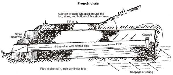
Figure 20—Wrapping French drains with geotextile
helps prevent clogging.
French drains or underdrains
are used to drain springs and seeps that
have a low flow.
Log culverts were used where stone (and stone masons) were not as readily available as logs. Construction crews may also have been more familiar with log construction. Log and timber culverts require less skill to build than stone culverts, but need maintenance. Expect to replace log culverts in 20 to 40 years, although they can last much longer.
Building a timber culvert is simple. We typically use 6 by 6 and 4 by 6 timbers, cutting them to any length suitable for the site and trail condition. Although old railroad culverts sloped the invert of their culverts, it may be difficult to do so in a wetland. In fact, it may be wise to build the invert level. This way the rising water from a creek or river can easily flow through the culvert as the water rises and recedes during a flood.
To build a timber culvert, two timber sleepers are placed in a shallow trench on each side of the trail, parallel to the trail centerline. The sleepers are pinned to the ground with at least two driftpins (figure 21). A timber wall is constructed on each side of the invert, resting on both sleepers. These walls can be as high or low as is suitable for the site condition. Notched 4 by 6 timbers are placed on the top of the walls to become the trail tread. The 4 by 6 timbers are spiked or pinned to the walls. Depending on materials available, the invert may be lined with stone or with planks resting on the sleepers. The invert should be flush with the bottom of the creek or wetland to allow aquatic organisms to move freely.
Normally, timber walls require deadmen going back perpendicular from the face of the wall into the earth behind the wall. The deadmen help keep the wall from collapsing. Because the walls for a timber culvert are only 6 to 8 feet long, installing deadmen is impractical. However, some bracing is needed to keep the walls from collapsing. For timber culverts with walls retaining 12 to 24 inches of earth, 4 by 6 timbers can be used for each side of the tread surface. The bottom of each 4 by 6 can be notched 1 inch deep at each end to fit over the two timber walls, forming a brace to support the walls. The area between these two 4 by 6s can be filled with 3-inch-wide planks (figure 22). Timber walls retaining more than 24 inches of earth should have notched 4 by 6s the full width of the tread surface.
Most lumberyards carry 4 by 6s only in 8-foot lengths. For efficient use of the wood, the 4 by 6s should be used to span distances of 8 feet, 4 feet, or 2 feet, 8 inches. The 2-foot, 8-inch length would provide a 20-inch-wide open area and is the minimum width recommended for timber culverts. The minimum clear height of the culvert should be 7 inches. Rough sawn 2-inch-wide lumber is adequate for the entire tread surface of the 2-foot, 8-inch culvert (figure 23).
The trail tread can be the surface of the top timbers of the culvert, or a curb can be added on each side and the space between the curbs can be filled with earth. The height and width of a timber culvert can be adjusted to fit site conditions and the expected volume of water. The spacing and number of culverts can also be adjusted to reduce the concentration of runoff and potential erosion problems. Timber culverts have an advantage over round pipe because the top timbers can be quite low and still provide the cross-sectional area of a large round pipe. Round pipe also concentrates runoff, while timber culverts spread the same volume of water over a wider area. Timber culverts work well with turnpike construction. Round pipe requires taller structures, a disadvantage.

Figure 21—Timber culvert. The invert (bottom of the culvert) is often
built
level in wetlands because it is less likely to wash away in floods.

Figure 22—Notching the deck planks on both ends of the culvert (two planks
with
notches are adequate for a wall up to 24 inches high) helps to
brace the walls.

Figure 23—Minimum size recommendations for a wooden
culvert
designed to use standard timber sizes efficiently.
Often larger culverts
may be needed. This culvert has
no constructed invert.
Pipe is not a traditional or visually compatible material for some backcountry trail culverts. Also, it is difficult to clean a small-diameter pipe with a shovel. A typical shovel blade is 9 inches wide and requires many passes to clean out a 12-inch-diameter pipe. You can do the job more easily with the smaller-diameter combi (combination tool). Make the rectangular opening of a timber culvert 20 inches wide and it will be much easier to clean than a round pipe. Pipes as small as 2 inches in diameter have been used to carry surface runoff beneath turnpike (appendix C compares round and rectangular culverts). Such pipes plug up within weeks and are impossible to clean. They should never have been installed.
Corrugated plastic culverts are sturdy, lightweight, and easy to cut. Although the culverts are not natural, the colors usually blend in with their surroundings better than steel. High-density polyethylene (HDPE) plastic culverts have become quite popular for trail work. However, some trail designers feel corrugated plastic culverts look out of place and they may not meet Recreational Opportunity Spectrum guidelines in remote sites. The ends can be framed by rock so they look natural, and plastic does not decay.
Timbers or logs used in culvert construction should be naturally decay-resistant or treated wood to help meet sustainability criteria. Treated wood should meet best management practices for aquatic environments.
Another culvert design that can be effective is an open-bottom culvert, essentially half of a round culvert. Openbottom culverts need to be adequately supported under both edges.