

Plans for Trail and Trail Bridge Structures
The USDA Forest Service Standard Trail Plans and Specifications are the design, construction, and maintenance of National Forest System trails and trail bridges. These plans and specifications are available to all, including other federal, state, and local agencies, communities, trail partners, and volunteers.
The Standard Trail Plans and Specifications reflect current Forest Service trail management efforts and the agency’s definitions of constructed features and tasks. The Forest Service’s National Technology and Development Program developed them in conjunction with the agency’s National Trails Program, with funding and support from the Federal Highway Administration’s Recreational Trails Program. These Standard Trail Plans and Specifications supersede the 1996 USDA Forest Service, Standard Drawings and Specifications for Construction and Maintenance of Trails.
3D Models
3D models of a few common trail structures are available on the American Trails webpage.

Climbing Turn 3D Model Stills (ZIP, 10.6 MB)

Crib Wall 3D Model Stills (ZIP, 18 MB)


Puncheon (ZIP, 25 MB)
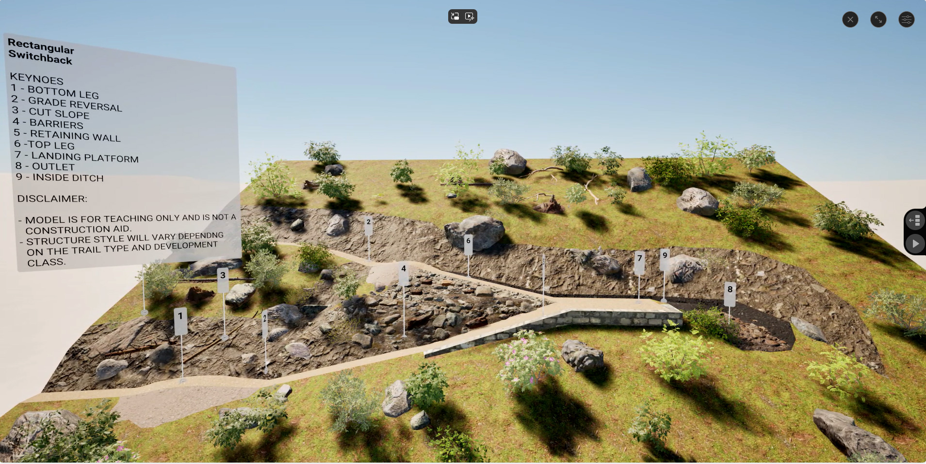
Rectangular Switchback (ZIP, 19 MB)
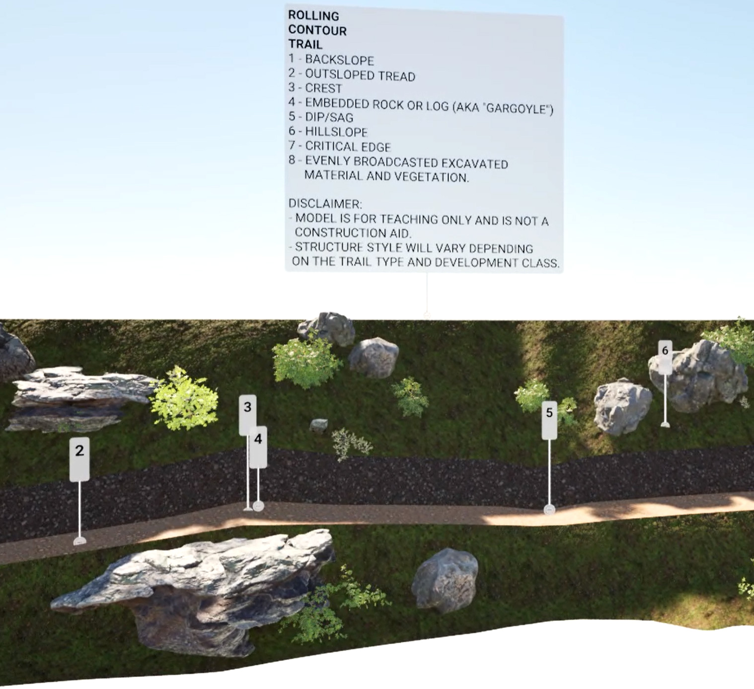
Rolling Contour Trail (ZIP, 16 MB)
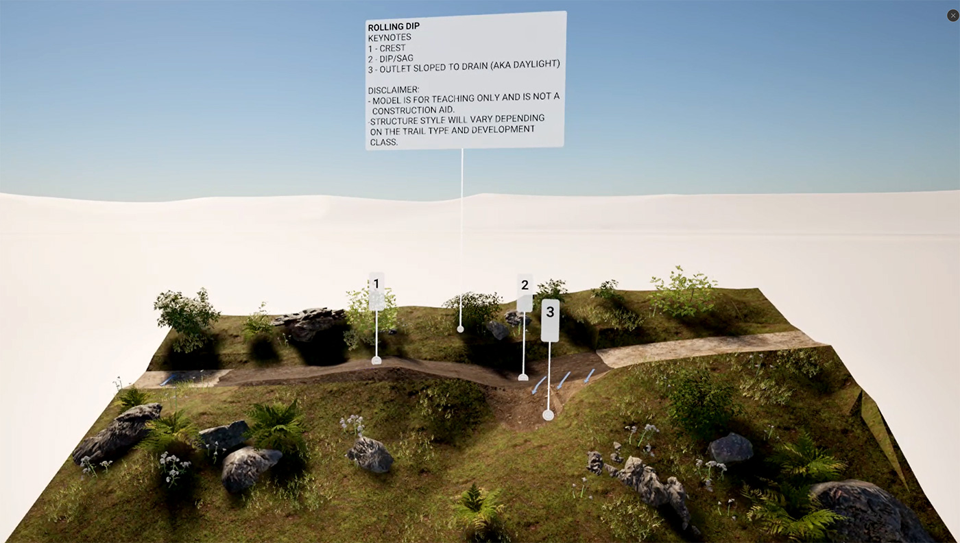
Rolling Dip (ZIP, 17 MB)
How to Use Plans and Specifications
The Standard Trail Plans and Specifications were developed to assist with trail design, construction, maintenance, inventory, condition assessment, and the assembly of trail construction plan packages. The Standard Trail Plans and Specifications include specifications, pay items, and plans.
Specifications and Pay Items
Specifications (PDF and Word)
Specifications are written requirements for performing work.Pay Items (PDF and Word)
Pay Items are specific items of work for which a unit and price are provided in a contract.
Plans
The Standard Trail Plans are comprised of Standard Trail Drawings that show the location, type, dimensions, and details of trail work.
The Standard Trail Plans are provided in United States customary units and are available below as PDFs (portable document files) and AutoCAD files. In AutoCAD, when using a postscript printer, this STD.ctb file should be used so line weights print as displayed (STD.zip).
The Standard Trail Drawings are to be used as-is, with trail and site-specific dimensional needs additionally recorded on each sheet. If the Standard Trail Drawings are modified, the title block must be changed to “Special Project Specifications ” to reflect the change.
The Forest Service Standard Trail Plans are available as compiled sets of PDFs or as individual drawings.
Compiled PDFs
Trail Plans (PDF, 17.7 MB)
Trail Bridge Plans (PDF, 12.4 MB)
Individual Drawings
The Standard Trail Plans and Specifications were developed to assist with trail design, construction, maintenance, inventory, condition assessment, and the assembly of trail construction plan packages. The Standard Trail Plans and Specifications include specifications, pay items, and plans.
This section contains standard drawings that are normally included in every trail or trail bridge plan package, such as the title sheet, vicinity map, work list, etc.
| Preview (PDF) | Drawing (AutoCAD) | Drawing Name | Date |
|---|---|---|---|
| Preview | STD_900-01 | Title Sheet | 11/05/2014 |
| Preview | STD_900-02 | Vicinity Map | 11/05/2014 |
| Preview | STD_900-03 | General Notes | 11/17/2014 |
| Preview | STD_900-04 | Work List | 11/05/2014 |
| Preview | STD_900-05 | Line Diagram | 11/05/2014 |
| Preview | STD_900-06 | Line Diagram | 11/05/2014 |
| Preview | STD_900-07 | Plan and Profile 10 | 11/05/2014 |
| Preview | STD_900-08 | Plan and Profile 20 | 11/05/2014 |
| Preview | STD_906-01 | Summary Quantity | 11/05/2014 |
This section includes standard plans for work items involving earthwork, such as excavation and embankment, clearing and grubbing, surfacing, fords, etc.
| Preview (PDF) | Drawing (AutoCAD) | Drawing Name | Date |
|---|---|---|---|
| Preview | STD_910-01 | Standard Trail Terms | 11/05/2014 |
| Preview | STD_911-01 | Typical Cross Section and Slope Finish | 11/05/2014 |
| Preview | STD_911-02 | Typical Obstruction Clearance Section | 11/05/2014 |
| Preview | STD_911-03 | Retainers | 11/05/2014 |
| Preview | STD_911-30-01 | Existing Trail Restoration | 11/05/2014 |
| Preview | STD_911-60-01 | Obliteration of Trails | 11/05/2014 |
| Preview | STD_912-01 | Clearing Limits Trees Logs | 11/05/2014 |
| Preview | STD_912-02 | Clearing Limits Brushing | 11/05/2014 |
| Preview | STD_913-01 | Typical Surfacing Sections | 11/05/2014 |
| Preview | STD_913-02 | Typical Surfacing Section with Retainers | 11/05/2014 |
| Preview | STD_913-03 | Typical Hardened Surfacing Sections | 11/05/2014 |
| Preview | STD_913-04 | Typical Hardened Surfacing Sections with Retainers | 11/05/2014 |
| Preview | STD_913-40-01 | Grid Unit Surfacing | 11/05/2014 |
| Preview | STD_913-50-01 | Riprap Surfacing | 11/05/2014 |
| Preview | STD_914-01 | Climbing Turn | 11/05/2014 |
| Preview | STD_915-01 | Talus Section | 11/05/2014 |
| Preview | STD_916-01 | Turnout and Passing Section | 11/05/2014 |
| Preview | STD_917-10-01 | Natural Ford | 11/05/2014 |
| Preview | STD_917-20-01 | Constructed Ford Rock Structure | 11/05/2014 |
| Preview | STD_917-20-02 | Constructed Ford Rock Structure | 11/05/2014 |
| Preview | STD_917-30-01 | Constructed Ford Log Structure | 11/05/2014 |
| Preview | STD_917-30-02 | Constructed Ford Log Structure | 11/05/2014 |
| Preview | STD_918-10-01 | Rock Foundations | 11/05/2014 |
| Preview | STD_918-20-01 | Gabion Basket Foundations | 11/05/2014 |
| Preview | STD_918-30-01 | Crib Foundations | 11/05/2014 |
| Preview | STD_918-40-01 | Geosynthetic Foundations | 11/05/2014 |
| Preview | STD_918-50-01 | Corduroy Foundations | 11/05/2014 |
This section includes standard drawings for work items involved with diverting water from the trail, such as water bars, culverts, ditches, etc.
| Preview (PDF) | Drawing (AutoCAD) | Drawing Name | Date |
|---|---|---|---|
| Preview | STD_921-10-01 | Standard Culvert | 11/05/2014 |
| Preview | STD_921-20-01 | Standard Culvert with Headwalls | 11/05/2014 |
| Preview | STD_921-30-01 | Rock Culvert | 11/05/2014 |
| Preview | STD_921-40-01 | Treated Timber Box Culvert | 11/05/2014 |
| Preview | STD_921-50-01 | Open Top Box Culvert | 11/05/2014 |
| Preview | STD_921-60-1 | Bottomless Arch Culvert with Rock Headwall | 11/05/2014 |
| Preview | STD_921-70-01 | Log Culverts | 11/05/2014 |
| Preview | STD_922-10-01 | Rock Waterbar | 11/05/2014 |
| Preview | STD_922-20-01 | Log or Timber Waterbar | 11/05/2014 |
| Preview | STD_922-30-01 | Belted Waterbar | 11/05/2014 |
| Preview | STD_923-10-01 | Rock Spillway | 11/05/2014 |
| Preview | STD_924-10-01 | Rock Underdrain | 11/05/2014 |
| Preview | STD_924-20-01 | Sheet Underdrain | 11/05/2014 |
| Preview | STD_924-20-02 | Sheet Underdrain with Outlet Pipe | 11/05/2014 |
| Preview | STD_925-01 | Typical Ditch Sections | 11/05/2014 |
| Preview | STD_926-01 | Berms | 11/05/2014 |
| Preview | STD_927-01 | Drain Dip | 11/05/2014 |
| Preview | STD_927-02 | Drain Dip Details | 11/05/2014 |
| Preview | STD_928-10-1 | Check Dam | 11/05/2014 |
This section includes standard drawings for a wide variety of constructed trail structures, including switchbacks, turnpike, side barriers, puncheon, retaining walls, etc.
| Preview (PDF) | Drawing (AutoCAD) | Drawing Name | Date |
|---|---|---|---|
| Preview | STD_931-10-01 | Type 1 Radius Switchback | 11/05/2014 |
| Preview | STD_931-20-01 | Type 2 Circular Landing Switchback | 11/05/2014 |
| Preview | STD_931-30-01 | Type 3 Rectangular Landing Switchback | 11/05/2014 |
| Preview | STD_932-10-01 | Standard Turnpike | 11/05/2014 |
| Preview | STD_932-20-01 | Type 2 Standard Turnpike with Foundation | 11/05/2014 |
| Preview | STD_933-10-01 | Stacked Rock Barrier | 11/05/2014 |
| Preview | STD_933-20-01 | Masonry Rock Barrier | 11/05/2014 |
| Preview | STD_933-20-02 | Concrete Masonry Unit Barrier | 11/05/2014 |
| Preview | STD_933-30-01 | Barrier Rail Grade | 11/05/2014 |
| Preview | STD_933-40-01 | Barrier Rail Post | 11/05/2014 |
| Preview | STD_933-40-02 | Timber Barrier On Post | 11/05/2014 |
| Preview | STD_933-50-01 | Curbs | 11/05/2014 |
| Preview | STD_933-60-01 | Guardrail | 11/05/2014 |
| Preview | STD_934-10-01 | Standard Puncheon | 11/05/2014 |
| Preview | STD_934-10-02 | Standard Puncheon | 11/05/2014 |
| Preview | STD_934-20-01 | Puncheon without Decking | 11/05/2014 |
| Preview | STD_935-10-01 | Log Crib | 11/05/2014 |
| Preview | STD_935-20-01 | Stacked Rock Retaining Wall | 11/05/2014 |
| Preview | STD_935-30-01 | Gabion Basket Retaining Wall | 11/05/2014 |
| Preview | STD_935-40-01 | Masonry Rock Retaining Wall | 11/05/2014 |
| Preview | STD_935-40-02 | Concrete Masonry Unit Retaining Wall | 11/05/2014 |
| Preview | STD_935-50-02 | Cast-In-Place Retaining Wall | 11/05/2014 |
| Preview | STD_936-10-01 | Individual Timber Pin Step | 11/05/2014 |
| Preview | STD_936-10-02 | Individual Rock Step | 11/05/2014 |
| Preview | STD_936-20-01 | Individual Overlap Rock Step | 11/05/2014 |
| Preview | STD_936-20-02 | Individual Overlap Timber Step | 11/05/2014 |
| Preview | STD_936-30-01 | Crib Ladder | 11/05/2014 |
| Preview | STD_936-40-01 | Staircase | 11/05/2014 |
| Preview | STD_937-10-01 | Railing System | 11/05/2014 |
| Preview | STD_938-10-01 | Standard boardwalk | 11/05/2014 |
| Preview | STD_938-10-02 | Standard boardwalk | 11/05/2014 |
| Preview | STD_938-10-03 | Standard boardwalk | 11/05/2014 |
| Preview | STD_938-20-01 | Elevated boardwalk | 11/05/2014 |
| Preview | STD_938-20-02 | Elevated boardwalk | 11/05/2014 |
| Preview | STD_938-20-03 | Elevated boardwalk | 11/05/2014 |
| Preview | STD_938-20-04 | Elevated boardwalk | 11/05/2014 |
| Preview | STD_938-30-01 | Step And Run | 11/05/2014 |
This section includes standard drawings for work items intended to control and manage trail access, including fences, gates, bollards, etc.
| Preview (PDF) | Drawing (AutoCAD) | Drawing Name | Date |
|---|---|---|---|
| Preview | STD_941-10-01 | Post Wire Fence | 11/05/2014 |
| Preview | STD_941-20-01 | Post Rail Fence | 11/05/2014 |
| Preview | STD_941-30-01 | Woven Wire Fence | 11/05/2014 |
| Preview | STD_941-40-01 | Jackleg Fence | 11/05/2014 |
| Preview | STD_941-50-01 | Stacked Rail Worm Fence | 11/05/2014 |
| Preview | STD_942-10-01 | Wire Gate | 11/05/2014 |
| Preview | STD_942-10-02 | Woven Wire Gate | 11/05/2014 |
| Preview | STD_942-20-01 | Metal Swing Gate | 11/05/2014 |
| Preview | STD_942-20-02 | Wood Swing Gate | 11/05/2014 |
| Preview | STD_942-20-03 | Wood Swing Gate | 11/05/2014 |
| Preview | STD_942-30-01 | Loose Rail Gate | 11/05/2014 |
| Preview | STD_942-40-01 | Accessible Kissing Gate | 11/17/2014 |
| Preview | STD_942-40-02 | Accessible Kissing Gate | 11/17/2014 |
| Preview | STD_942-50-01 | Accessible Gates Chicanes | 11/05/2014 |
| Preview | STD_944-10-01 | Stiles | 11/05/2014 |
| Preview | STD_945-10-01 | Bollards | 11/05/2014 |
This section includes standard drawings for signs, route markers, reassurance markers, mileage markers, and cairns.
| Preview (PDF) | Drawing (AutoCAD) | Drawing Name | Date |
|---|---|---|---|
| Preview | STD_950-01 | Sign Layout | 11/05/2014 |
| Preview | STD_951-01 | Sign Posts Installation | 11/05/2014 |
| Preview | STD_951-02 | Sign Posts Installation | 11/05/2014 |
| Preview | STD_952-01 | Route Markers | 11/05/2014 |
| Preview | STD_953-01 | Reassurance Markers | 11/05/2014 |
| Preview | STD_955-01 | Rock Cairn | 11/05/2014 |
This section includes standard trail bridge plans for timber and prefabricated steel bridges.
Standard trail bridge plans for timber and prefabricated steel bridges have been approved by Forest Service Washington Office Director of Engineering and Washington Office Director of Recreation for use on National Forest System lands. The standard trail bridge plans are for typical superstructure designs and abutment details commonly used. The plans are not meant to be used as individual drawings. The designer should download all associated plans for the bridge type to ensure they have a complete trail bridge package.
A qualified engineer with trail bridge design experience must approve the use of these Standard Trail Bridge plans for each trail bridge project. Proper bridge siting and design includes many other aspects such as siting, hydrology, hydraulics, foundation, etc. Forest Service Trail Bridge design requirements are found in Forest Service Directives Forest Service Manual (FSM) 7723 and Forest Service Handbook (FSH) 7709.56b, Chapter 80 and in Technology and Development Center’s publication “Locating Your Trail Bridge for Longevity”.
On Forest Service projects, these plans may not be modified without Regional Engineer approval (except for populating the Structure Table on page 1 for each bridge type).
Non-Forest Service entities are welcome to use these trail bridge plans, but must take full responsibility for their use. We further recommend they seek review and approval from their qualified engineer of record for the project.
Trail Bridge Plans are provided below in a combination of editable AutoCAD .dwg and non-editable .dwf formats. Regional Bridge Engineers retain editable .dwg versions of the AutoCAD .dwf plans provided here.
| Preview (PDF) | Drawing (AutoCAD) | Drawing Name | Date |
|---|---|---|---|
| (PDF, 1.01 MB) | Not Applicable | Single Log Stringer Trail Bridge (Compiled Drawings: STD_961-10-01 to STD_961-10-04) | 11/05/2014 |
| (PDF, 420 KB) | STD_961-10-01 | Structure Table | 11/05/2014 |
| Preview | STD_961-10-02 | Typical Section Details | 11/05/2014 |
| Preview | STD_961-10-03a | General Notes / Design Table (Douglas Fir) | 11/05/2014 |
| Preview | STD_961-10-03b | General Notes / Design Table (Southern Pine) | 11/05/2014 |
| Preview | STD_961-10-04 | Abutment Details | 11/05/2014 |
| Preview | Not Applicable | Multiple Log Stringer Trail Bridge (Compiled Drawings: STD_961-20-01 to STD_961-20-06) | 11/05/2014 |
| Preview | STD_961-20-01 | Structure Table | 11/05/2014 |
| Preview | STD_961-20-02a | General Notes (Douglas Fir) | 11/05/2014 |
| Preview | STD_961-20-02b | General Notes (Southern Pine) | 11/05/2014 |
| Preview | STD_961-20-03a | Typical Superstructure / Design Table (Douglas Fir) | 11/05/2014 |
| Preview | STD_961-20-03b | Typical Superstructure / Design Table (Southern Pine) | 11/05/2014 |
| Preview | STD_961-20-04 | Cross-Section Details | 11/05/2014 |
| Preview | STD_961-20-05 | Cross-Section Details / Abutment Details | 11/05/2014 |
| Preview | STD_961-20-06 | Abutment Details | 11/05/2014 |
| Preview | Not Applicable | Sawn Timber Stringer Trail Bridge (Compiled Drawings: STD_962-10-01 to STD_962-10-04) | 11/05/2014 |
| Preview | STD_962-10-01 | Structure Table | 11/05/2014 |
| Preview | STD_962-10-02a | Typical Superstructure / Design Table (Douglas Fir) | 11/05/2014 |
| Preview | STD_962-10-02b | Typical Superstructure / Design Table (Southern Pine) | 11/05/2014 |
| Preview | STD_962-10-03a | Cross-Section Details / General Notes (Douglas Fir) | 11/05/2014 |
| Preview | STD_962-10-03b | Cross-Section Details / General Notes (Southern Pine) | 11/05/2014 |
| Preview | STD_962-10-04 | Abutment Details | 11/05/2014 |
| Preview | Not Applicable | Longitudinal Nail-Laminated Timber Trail Bridge (Compiled Drawings: STD_962-20-01 to STD_962-20-05) | 11/05/2014 |
| Preview | STD_962-20-01 | Structure Table | 11/05/2014 |
| Preview | STD_962-20-02a | Cross-Section Details / General Notes (Douglas Fir) | 11/05/2014 |
| Preview | STD_962-20-02b | Cross-Section Details / General Notes (Southern Pine) | 11/05/2014 |
| Preview | STD_962-20-03a | Typical Layout - 12 Feet Long | 11/05/2014 |
| Preview | STD_962-20-03b | Typical Layout - 16 Feet Long | 11/05/2014 |
| Preview | STD_962-20-03c | Typical Layout - 20 Feet Long | 11/05/2014 |
| Preview | STD_962-20-04a | Typical Superstructure / Design Table (Douglas Fir) | 11/05/2014 |
| Preview | STD_962-20-04b | Typical Superstructure / Design Table (Southern Pine) | 11/05/2014 |
| Preview | STD_962-20-05 | Abutment Details | 11/05/2014 |
| Preview | Not Applicable | Glulam Stringer Trail Bridge (Compiled Drawings: STD_963-10-01 to STD_963-10-04) | 11/05/2014 |
| Preview | STD_963-10-01 | Structure Table | 11/05/2014 |
| Preview | STD_963-10-02a | Typical Sections / Design Table - 2 Beam (Douglas Fir) | 11/05/2014 |
| Preview | STD_963-10-02b | Typical Sections / Design Table - 2 Beam (Southern Pine) | 11/05/2014 |
| Preview | STD_963-10-02c | Typical Sections / Design Table - 3 Beam (Douglas Fir) | 11/05/2014 |
| Preview | STD_963-10-02d | Typical Sections / Design Table - 3 Beam (Southern Pine) | 11/05/2014 |
| Preview | STD_963-10-03a | General Notes - 2 Beam (Douglass Fir) | 11/05/2014 |
| Preview | STD_963-10-03b | General Notes - 2 Beam (Southern Pine) | 11/05/2014 |
| Preview | STD_963-10-03c | General Notes - 3 Beam (Douglass Fir) | 11/05/2014 |
| Preview | STD_963-10-03d | General Notes - 3 Beam (Southern Pine) | 11/05/2014 |
| Preview | STD_963-10-04 | Abutment Details | 11/05/2014 |
| Preview | Not Applicable | Longitudinal Glulam Deck Panel Trail Bridge (Compiled Drawings: STD_963-20-01 to STD_963-20-04) | 11/05/2014 |
| Preview | STD_963-20-01 | Structure Table | 11/05/2014 |
| Preview | STD_963-20-02a | Typical Sections / Design Table (Douglas Fir) | 11/05/2014 |
| Preview | STD_963-20-02b | Typical Sections / Design Table (Southern Pine) | 11/05/2014 |
| Preview | STD_963-20-03a | Cross-Section Details / General Notes (Douglas Fir) | 11/05/2014 |
| Preview | STD_963-20-03b | Cross-Section Details / General Notes (Southern Pine) | 11/05/2014 |
| Preview | STD_963-20-04 | Abutment Details | 11/05/2014 |
| Preview | Not Applicable | Prefabricated Steel Trail Bridge (Compiled Drawings: STD_964-10-01 to STD_964-10-03) | 11/05/2014 |
| Preview | STD_964-10-01 | Structure Table | 11/05/2014 |
| Preview | STD_964-10-02a | General Notes (Douglas Fir) | 11/05/2014 |
| Preview | STD_964-10-02b | General Notes (Southern Pine) | 11/05/2014 |
| Preview | STD_964-10-03 | Abutment Details | 11/05/2014 |
| Preview | Not Applicable | Substructure (Compiled Drawings: STD_965-10-01 to STD_965-40-01) | 11/05/2014 |
| Preview | STD_965-10-01 | Timber Sill On Geocell Pad | 11/05/2014 |
| Preview | STD_965-20-01 | Timber Sill On Gabion Basket | 11/05/2014 |
| Preview | STD_965-30-01 | Timber Sill On Timber Cribbing | 11/05/2014 |
| Preview | STD_965-40-01 | Concrete Leveling Pad On Bedrock | 11/05/2014 |
This section does not include any standard drawings, but is reserved and used for the identification of specialty structures in project packages, such as tunnels, snow sheds, etc. Refer to Specifications Section 970 - Specialty Structures.
This section includes standard drawings for work items that are considered incidental to major work items, such as seeding, fertilizing and mulching, removal of structures, etc.
| Preview (PDF) | Drawing (AutoCAD) | Drawing Name | Date |
|---|---|---|---|
| Preview | STD_981-01 | Seeding and Mulching | 11/05/2014 |
This section does not include any standard drawings, but includes material specifications used for work items included in project package. Examples include aggregate, rock, geosynthetics, material for timber structures, etc. Refer to Specifications Section 990 - Materials.
Related Reference Materials
Federal Trail Data Standards
USDA Forest Service National Technology and Development: Program and Publications
For More Information
Please contact USDA Forest Service Trail Management if you have questions or comments.
Acknowledgments
These Standard Trail Plans and Specifications were revised and developed with extensive involvement and expertise from Jonathan Kempff, P.E. (Professional Engineer), Forest Service National Trail Technical Team; and James Scott Groenier, P.E., and Deb Mucci, Draftsperson, both with Forest Service Technology and Development Program. This project was sponsored and funded in large part by the Federal Highway Administration, Recreational Trails Program.
Forest Service Disclaimer
The Forest Service, an agency of the U.S. Department of Agriculture (USDA), has developed this information for the guidance of its employees, its contractors, and its cooperating Federal and State agencies. The Forest Service assumes no responsibility for the interpretation or use of this information by anyone except its own employees. The use of trade, firm, or corporation names is for the information and convenience of the reader. Such use does not constitute an official endorsement or approval of any product or service to the exclusion of others that may be suitable.
Federal Highway Administration Notice
These materials were produced in cooperation with the Recreational Trails Program of the U.S. Department of Transportation’s Federal Highway Administration in the interest of information exchange. The U.S. Government assumes no liability for the use of information contained in this document. The U.S. Government does not endorse products or manufacturers. Trademarks or manufacturers’ names appear in this report only because they are considered essential to the objective of this document. These materials reflect the views of the authors, who are responsible for the facts and accuracy of the data presented herein. The contents do not necessarily reflect the official policy of the U.S. Department of Transportation.